background image

SMA


Technologie AG

Unit description

Operating instructions

WB11_17-11:FE4205

Page 19

3.3.4 Description of the operational status

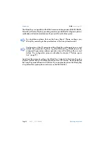
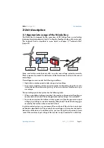
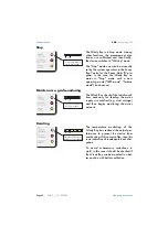
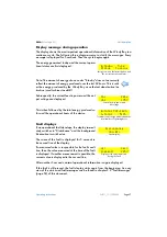
No (or low) input voltage

The Windy Boy is in Standby mode. This
situation occurs when the input perfor-
mance is too low for feeding the mains
grid (DC input voltage < approx. 80 V)
and for satisfying the on-board power re-
quirements.

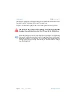
Initialization

The on-board computer of the Windy
Boy is presently in the initialization pro-
cess. The DC input voltage of the Windy
Boy lies between approx. 80 V and ap-
prox. 120 V. The power is adequate for
the on-board power requirements but in-
sufficient for mains-grid feed-in or for
data transmission.

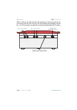
Working mode

The Windy Boy has successfully passed
the measurement electronics and SMA
grid guard self-tests and has begun feed-
in operation.

The Windy Boy is working normally and
is feeding electricity into the mains grid.
It is converting the DC voltage from the
wind turbine according to the V/I char-
acteristic curve defined by <U

PV

Start>,

<U

DC

WindStart> and <U

DC

WindMax>

(chapter 5 “Turbine operation" on
page 31)
.

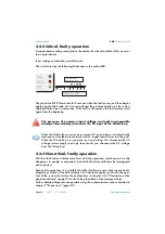
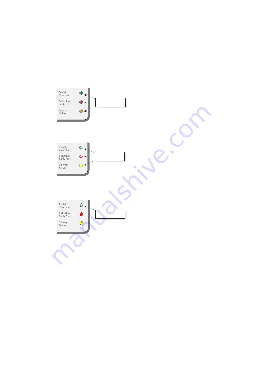
All LEDs are off.

All LEDs are on.

Green LED is on.

Summary of Contents for Windy Boy 1100

Page 1: ...Windy Boy 1100 Windy Boy 1700 Inverter for Wind Energy Power Plants Operating Instructions Version 1 0 WB11_17 11 FE4205 TBE WB11 17...

Page 2: ......

Page 3: ...SMA Technologie AG Revision History Operating Instructions WB11_17 11 FE4205 Page 3 Revision History Document number Changes Author WB11_17 11 FE4205 First issue Welzel...

Page 4: ...SMA Technologie AG Page 4 WB11_17 11 FE4205 Operating Instructions...

Page 5: ...for a trouble free and safe operation of the product Please read these sections care fully in order to avoid any damages of the equipment and for op timal personal protection This symbol indicates in...

Page 6: ...d protection Arbitrary changing of the product or the provided software Failure of the product due to interference of connected or contiguous devices out of legal limit values Disasters and force maje...

Page 7: ...5 1 Overview 31 5 2 Characteristic curve function 31 5 3 Characteristic curve operation in Turbine operating mode 34 5 4 General setting example 35 6 Maintenance and care 37 7 Expansions 39 7 1 Sunny...

Page 8: ...connection data 51 8 2 3 General data 52 9 General information 53 9 1 Measurement channels and messages 53 9 1 1 Status messages 54 9 1 2 Windy Boy operating parameters 55 9 2 Fault messages 58 9 3 De...

Page 9: ...n norms as confirmed in the CE conformity declaration 9 3 Declaration of conformity CE page 61 The documentation provided here covers all such topics that are of interest when op erating the Windy Boy...

Page 10: ...be used as a PV inverter Please download the Sunny Boy manual from www SMA de If you are planning to use the Windy Boy in a photovoltaic system please contact us on the SMA hotline For stand alone sy...

Page 11: ...of the heatsink can reach over 60 C in normal operation There is the danger of burn injury when these parts are touched The Windy Boy contains an independent mains disconnection device the SMA grid g...

Page 12: ...Safety Information SMA Technologie AG Page 12 WB11_17 11 FE4205 Operating instructions...

Page 13: ...of mains interference or po wer outage The overvoltage protection system has the following tasks When a pre defined voltage is reached the inverter is disconnected from the ge nerator and a short cir...

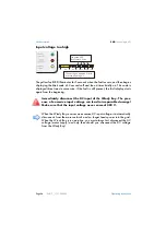
Page 14: ...the right to all warranty claims The presence of excessive input voltage can lead to irreparable damage Immediately disconnect the DC input of the Windy Boy When the Windy Boy receives an excessive D...

Page 15: ...can be operated without any further modification or configuration The device parameters can however be modified if required An extra communications interface is required for ideal adapta tion of the...

Page 16: ...well as any optional com munications connections are to be found on the underside of the Windy Boy Each of the and DC connections are internally connected in parallel within the Windy Boy Plug connec...

Page 17: ...te description of the possible displays can be found in chapter 3 3 4 De scription of the operational status page 19 These can be split into three catego ries 3 3 1 Normal operation As long as the gre...

Page 18: ...rrected Despite all precautions it is possible that other faults may occur that cannot be dis played e g failure of the status display In order to recognize such faults the oper ator of the system sho...

Page 19: ...DC input voltage of the Windy Boy lies between approx 80 V and ap prox 120 V The power is adequate for the on board power requirements but in sufficient for mains grid feed in or for data transmissio...

Page 20: ...ance grid monitoring The Windy Boy checks if the initial condi tions necessary for feeding the mains supply are satisfied e g start voltage and then begins monitoring the mains network Derating The te...

Page 21: ...oring and or the in dependent disconnection device SMA grid guard The Sunny Boy has detected a fault in the SMA grid guard during an internal test and has disabled the mains supply feed in This usuall...

Page 22: ...can have the following causes Low mains supply voltage VAC Vac Min High mains supply voltage VAC Vac Max Low mains supply frequency fAC Fac Min High mains supply frequency fAC Fac Max A change in main...

Page 23: ...the beginning The Windy Boy has detected a fault relating to an unacceptable impedance in the mains supply If the Windy Boy frequently displays this fault during mains monitoring the cause can be a ma...

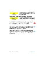
Page 24: ...connect the DC input of the Windy Boy The pres ence of excessive input voltage can lead to irreparable damage Make sure that the input voltage never exceeds 400 V When the Windy Boy receives an excess...

Page 25: ...ode is displayed three times in succession If the fault is still present the fault display starts again from the beginning The Windy Boy is in a condition that prevents it from entering normal operati...

Page 26: ...isplay messages in the startup phase The following messages are displayed during the startup phase of the Windy Boy 1700 and are iden tical to those in the Windy Boy 1100 Since the Windy Boy is identi...

Page 27: ...esponsible for the fault condi tion then the value measured at the time of the fault is displayed If another measurement is possible the current value is displayed in the second line After another 5 s...

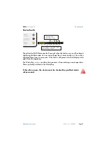
Page 28: ...amage Make sure that the input voltage never exceeds 400 V Before placing the device back into operation the input voltage must be checked before reconnecting the DC voltage to the Windy Boy Since the...

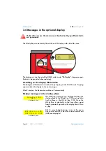
Page 29: ...ince the cover must be removed please ask a qualified electrician to disconnect the DC and AC connections from the Windy Boy ac cording to the installation instructions Language Switch S2 Switch S1 Ge...

Page 30: ...Setting the display language SMA Technologie AG Page 30 WB11_17 11 FE4205 Operating instructions...

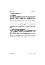
Page 31: ...ne is presented to the inverter in the form of a direct rotation speed variable DC voltage RPM and current intensity torque Most small wind turbines have a so called permanent magnet generator and a d...

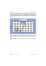
Page 32: ...meters UPVStart UDCWindStart and UDCWindMax are used to adapt the power voltage curve of the Windy Boy to the wind generator be ing used The correct configuration of the parameters shown in the diagra...

Page 33: ...00 VDC Defines the voltage at the moment when the Windy Boy is ready to begin feed ing power into the mains grid UdcWind Max 330 1 800 330 1 800 VDC Defines the voltage at the moment when the Windy Bo...

Page 34: ...ed the mains grid at maximum power The characteristic curve ends at the maximum permissible input voltage of the Windy Boy which must never be exceeded If the wind strength is so low that the DC input...

Page 35: ...nput voltage which avoids braking of the wind generator through excessive power consumption This set ting is especially suitable in locations with little or weak wind Once the properties of the wind g...

Page 36: ...Turbine operation SMA Technologie AG Page 36 WB11_17 11 FE4205 Operating instructions...

Page 37: ...age 19 In the interests of maximum yield the operator should check weekly if possible un der various conditions of wind if the display of the Windy Boy indicates plausible normal operation cf chapter...

Page 38: ...Maintenance and care SMA Technologie AG Page 38 WB11_17 11 FE4205 Operating instructions...

Page 39: ...separate RS232 cable using a wireless link Sunny Beam using a USB Service Interface USBPBS The wind turbine can be monitored by the Windy Boy in a number of different ways SMA offers a range of produ...

Page 40: ...lly occurs directly over the COM1 or COM2 port of the PC The installation of the RS232 cable is described in the installation instructions of the Windy Boy max 50 Betrieb Operation Erdschluss Earth Fa...

Page 41: ...ter SWR 1100 E Betrieb Operation Erdschluss Earth Fault St rung Failure Photovolta ik Stringw echselrich ter Photovolta ic string inverter SWR 1100 E Betrieb Operation Erdschluss Earth Fault St rung F...

Page 42: ...the PC is described in the Sunny Beam user manual Betrieb Operation Erdschluss Earth Fault St rung Failure Photovolta ik Stringw echselrich ter Photovolta ic string inverter SWR 1100 E Betrieb Operat...

Page 43: ...olta ic string inverter SWR 1100 E Betrieb Operation Erdschluss Earth Fault St rung Failure Photovolta ik Stringw echselrich ter Photovolta ic string inverter SWR 1100 E Betrieb Operation Erdschluss E...

Page 44: ...C The connection between the PC and the Sunny Boy Control can occur via modem if required Large sys tems with more than 50 Windy Boys can be monitored by coupling several Sunny Boy Controls together I...

Page 45: ...r www SUNNY PORTAL de Sunny WebBox LAN LAN PC PC via Modem External Display External Sensors Memory Card RS485 Powerline Radio RS232 Sunny Portal Internet LAN LAN Hub Telephone Connection Betrieb Oper...

Page 46: ...0 W Sunny TV Pac 7 450 W Video Projector TV Set Sunny TV Pac 7 450 W PC Monitor Video Out Sunny TV Sunny TV Pac 7 450 W Betrieb Operation Erdschluss Earth Fault St rung Failure Photovolta ik Stringwe...

Page 47: ...rent IDC max 10 A Max input power PDC max 1210 W Recommended generator pow er at 5000 full load hours year Pturb max 800 W Recommended generator pow er at 2500 full load hours year Pturb max 900 W All...

Page 48: ...e grid voltage UAC 198 260 V AC 180 265 V programmable Operating range grid frequen cy fAC 49 8 50 2 Hz 59 8 60 2 Hz 45 5 54 5 Hz 55 5 64 5 Hz programmable All pole isolator grid side Independent disc...

Page 49: ...t voltage the higher is the efficiency General data Protection type to DIN EN 60529 IP65 External temperature range 25 C to 60 C Dimensions w x h x d 322 mm x 320 mm x 180 mm Weight 21 kg approx Exter...

Page 50: ...t IDC max 12 6 A Max input power PDC max 1850 W Recommended generator power at 5000 full load hours year Pturb max 1240 W Recommended generator power at 2500 full load hours year Pturb max 1395 W All...

Page 51: ...ing range grid voltage VAC 198 260 V AC 180 265 V programmable Operating range grid frequency fAC 49 8 50 2 Hz 59 8 60 2 Hz 45 5 54 5 Hz 55 5 64 5 Hz programmable All pole isolator grid side Independe...

Page 52: ...age The lower the input voltage the higher the efficiency General data Protection type to DIN EN 60529 IP65 Dimensions w x h x d 434 mm x 295 mm x 214 mm Weight 25 kg approx External interfaces Data t...

Page 53: ...y Fac Grid frequency Faults Fault type display under Disturbance status h total Total hours of mains supply feed in operation Iac Ist Grid current Ipv DC current Netz Ein Total number of mains supply...

Page 54: ...Island as network controller More information about this topic can be obtained from the Sunny Island operating manual under the category Droop Mode grid mon Testing the mains supply status mains imped...

Page 55: ...mains network no operation Turbine Operating mode for wind turbines the input voltage is converted according to the V I function defined by UPVStart UDCWindStart and UDCWindMax Default GER ENS Used fo...

Page 56: ...a permanent fault Speicher n Store Storage Permanent volatile Permanent Permanent Modified parameters are stored in the EEPROM and can be used even when the Windy Boy has been restarted Volatile Prev...

Page 57: ...to the system 180 V is the recommended voltage for the Windy Boy 1100 and the Windy Boy 1700 Reducing this voltage parameter can lead to numerous unnecessary connection attempts Increasing this voltag...

Page 58: ...uring reading or writing of data from the EEPROM the data is not relevant for safe operation this fault has no effect on performance EEPROM dBh Data EEPROM is defective the device has switched itself...

Page 59: ...s exceeded the permissible range Bfr or Srr is an internal message that has no meaning for the user The Uac fault can have the following causes Mains supply disconnected circuit breaker or fuse Broken...

Page 60: ...dance is calculated from the mains supply impedance and the impedance of the mains connection cable AC cable of the Windy Boy Check the mains voltage and mains connections on the Windy Boy Use a mains...

Page 61: ...fabricated by SMA This especially applies for the EMC Regulation defined in 89 336 EWG and the low voltage regulation defined in 73 23 EWG The devices are compliant with the following standards EMC Em...

Page 62: ...11_17 11 FE4205 Operating instructions 9 4 Import certificate The Windy Boy string inverter is equipped with the SMA grid guard independent disconnection device and it is covered by the industrial tra...

Page 63: ...systems based on the Sunny Island The Windy Boy requires extra settings for this to ensure optimum operation and also to achieve deactivation of the standard mains grid monitoring settings Please obt...

Page 64: ...Stand alone systems SMA Technologie AG Page 64 WB11_17 11 FE4205 Operating instructions...

Page 65: ...the Windy Boy please contact our service hotline Please have the following information available when you contact SMA Inverter type Connected wind turbine Communication Serial number of the Windy Boy...

Page 66: ...Contact SMA Technologie AG Page 66 WB11_17 11 FE4205 Operating instructions...

Page 67: ......

Page 68: ...reecall 800 78669269 Sales SMA Solar Technology Rosendahl Industrievertretungen Adolf Dembach Strasse 1 47829 Krefeld Germany Tel 49 2151 45678 90 Fax 49 2151 45678 99 SMA Solar Technology China Inter...

Reviews: