SMA Solar Technology AG
Electrical Connection
Installation Manual
WB33-38-IA-IEN120940
21
5 Electrical Connection
5.1 Safety
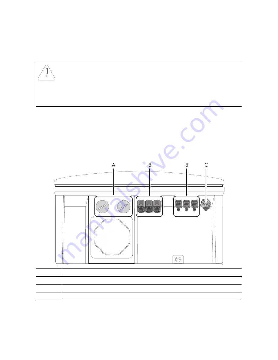
5.2 Overview of the Connection Area
5.2.1 Exterior View
The following figure shows the assignment of the individual connection areas on the underside of the
inverter.
* For WB 3300-11 / WB 3800-11, the inverter is fitted with 2 negative and 2 positive DC connectors.
NOTICE!
Electrostatic discharge can damage the inverter
Internal components of the inverter can be irreparably damaged by electrostatic
discharge.
• Earth yourself before touching a component.
Object
Description
A
Enclosure openings for communication (with filler-plugs)
B
DC connectors for connecting the DC cables*
C
AC socket for grid connection

