SMA
Technologie AG
Unit Description
User Manual
WB1100LV-11:FE2606
Page 15
4.3 Operating Modes
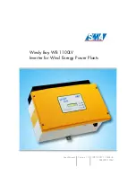
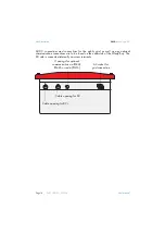
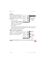
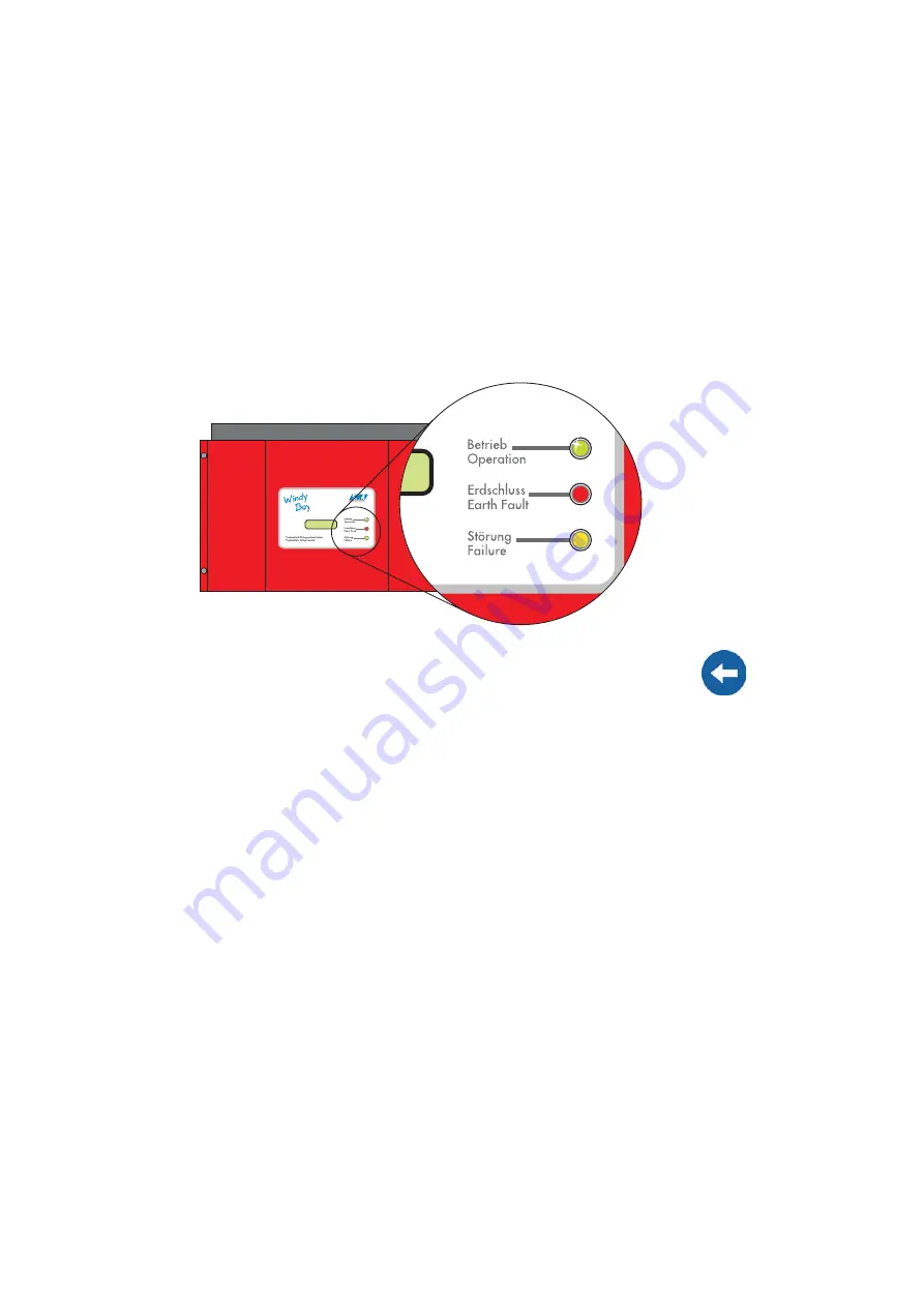
The various operating modes are displayed using three light-emitting diodes (LEDs) on
the housing cover of the Windy Boy. To allow the device to indicate its operating mode
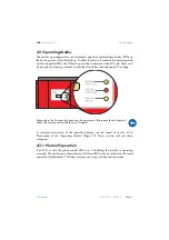
via the integrated LEDs, the Windy Boy must be connected on the DC side. There must
be enough wind energy present, so that the Windy Boy has adequate DC voltage.
A complete description of the possible displays can be found in section 4.3.4
"Description of the Operating Modes" (Page 17). These can be split into three
categories:
4.3.1 Normal Operation
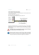
If no LED, or only the green control LED is on, or blinking, the inverter is operating
normally. The simultaneous illumination of all three LEDs is also an indication of normal
operation ("initialization"). All other displays are a sign of abnormal operation.
Especially in the first year of operation, the operator of the system should regularly
check this display under different wind speeds.
Summary of Contents for Windy Boy WB 1100LV
Page 2: ......
Page 6: ...Explanation of Symbols Used SMA Technologie AG Page 6 WB1100LV 11 FE2606 User Manual...
Page 10: ...Safety Instructions SMA Technologie AG Page 10 WB1100LV 11 FE2606 User Manual...
Page 28: ...Unit Description SMA Technologie AG Page 28 WB1100LV 11 FE2606 User Manual...
Page 30: ...Setting the Display Language SMA Technologie AG Page 30 WB1100LV 11 FE2606 User Manual...
Page 40: ...Turbine Operation SMA Technologie AG Page 40 WB1100LV 11 FE2606 User Manual...
Page 42: ...Maintenance and Care SMA Technologie AG Page 42 WB1100LV 11 FE2606 User Manual...
Page 50: ...Extensions SMA Technologie AG Page 50 WB1100LV 11 FE2606 User Manual...
Page 54: ...Technical Data SMA Technologie AG Page 54 WB1100LV 11 FE2606 User Manual...
Page 72: ...General Information SMA Technologie AG Page 72 WB1100LV 11 FE2606 User Manual...
Page 74: ...Stand Alone Systems SMA Technologie AG Page 74 WB1100LV 11 FE2606 User Manual...
Page 77: ......

