Small Wonder Labs
PSK-40 Transceiver Kit 03/09/10
2000
13
Group 2 Assembly:
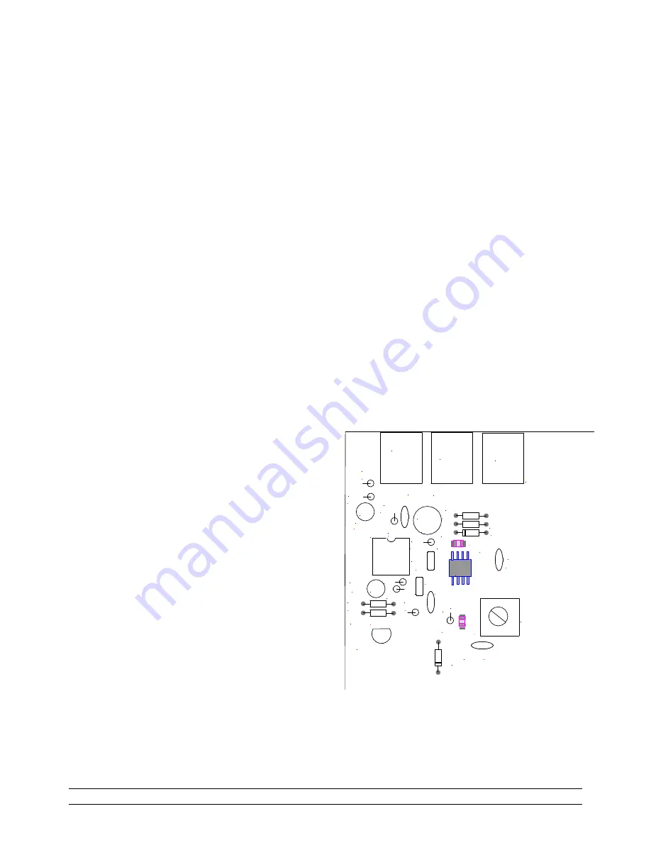
Group 2 assembly installs the receiver 'back-end'
circuitry.
Install 3.5 mm (1/8") audio jacks at J1-J3.
Install an 8-pin IC socket at U4. Match the
'notch' orientation as shown on the silkscreen.
Install R20 (220
Ω
, red/red/brown).
Install R19 (4.7K, ylw/violet/red).
Install electrolytic cap C18 (10 uF). Observe
the polarity marking on the device.
Install R16 (510K, green/brn/ylw).
Install R17 (10
Ω
, brown/blk/blk).
Install R14 (1K, brown/blk /red).
Install D8 (1N5236- from 'Zeners' envelope).
Match the orientation of the banded end of the
component to that of the silkscreen.
Install C17 (47 pF disk cap).
Install electrolytic cap C107 (220 uF).
Observe the polarity marking on the device.
Install C14 (.01 uF disk cap ), '103"'
Install C15 and C19 (.1 uF monolithic caps),
'104'
Install R15 (10K, brown/blk /orange).
Install C16 (.01 uF disk cap).
Install diodes D5 and D6 (1N4148). Observe
the installation polarity as shown on the
silkscreen.
Install electrolytic cap C20 (3.3 uF). Observe
the installation polarity as shown on the
silkscreen.
Install R21 (1 Megohm, brn/blk/green.)
Install R23 (10K, brn/blk/orange).
Install R22 (33K, orange/org/org).
Install R18 ((10K, brn/blk/orange).
Install C13 (220 pF disk cap).
Install D15 (1N4148). Match the orientation
of the banded end of the component to that of
the silkscreen.
Install IF transformer T1.
Caution
: Ensure
that you install the transformer marked
'42IF123' in this location.
The slug in this
transformer is colored green.
Install Q12 (2N7000- from antistatic bag).
Match the orientation of the flat side of the
component to that of the silkscreen.
This part
is static-sensitive
.
MICR.
T1
J1
J2
R20
R19
220
4.7K
C
1
8 - +
10 uF
- +
C20
3.3
D5
D6
U4
C17
R
1
6
47 pF
510K
- +
C107
U3
C106
.01
220 uF
R17
D8
R14
1K
10
C15
C
1
9
.01
.1
C
1
6
.01
R15
10K
Q12
R22
33K
R21
R23
10K
1M
C13
C
1
0
8
R18
220
10K
D
1
5
LINE
OUT
LINE
OUT
.1
C14
J3
SA
612


