Section 1 - Installation
1.19
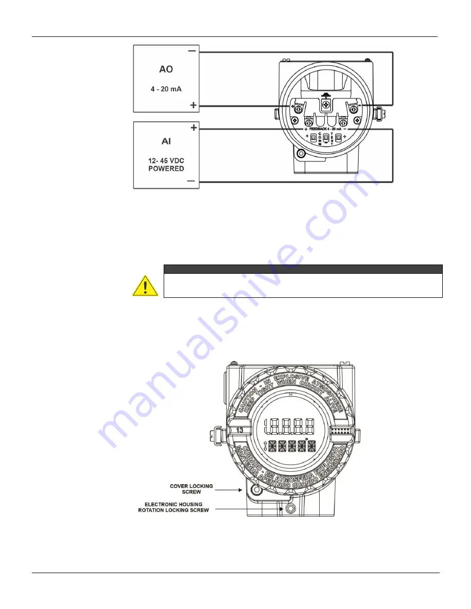
Figure 1.24
– Feedback connections
Electronic Housing Rotation
The electronic housing can be rotated to offer a better display position and/or better access to the
field cables.
WARNING
To avoid damage do not rotate the electronic housing more than 270º starting from the
fully threaded without disconnecting the electronic circuit from the printed circuit board
and from the power supply.
1. Loose the rotation locking screw. See figure 1.25
2. Rotates the electronic housing to the desired position. Observe if the flat cable is not excessively
twisted. See figure 1.26.
3. Tighten the rotation locking screw.
Figure 1.25
– Electronic housing rotation locking screw
Summary of Contents for HART FY500
Page 1: ......
Page 2: ......
Page 21: ...Section 1 Installation 1 15 Dimensional Drawings Figure 1 19 Dimensional drawings...
Page 30: ...FY500 HART Operation Maintenance and Installation Manual 1 24...
Page 34: ...FY500 HART Operation Maintenance and Installation Manual 2 4...
Page 38: ...FY500 HART Operation Maintenance and Installation Manual 3 4...
Page 41: ...Section 4 Local Programming 4 3 Local Programming Tree Figure 4 3 Local Programming Tree...
Page 59: ...Section 6 Maintenance 6 11 Exploded View Figure 6 6 Exploded View...


