FY500 HART – Operation, Maintenance, and Installation Manual
2.2
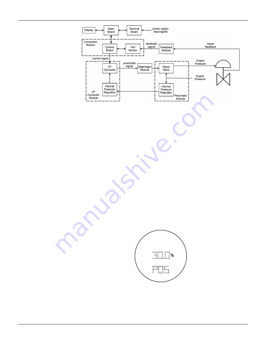
Figure 2.2 – FY500 Block Diagram
Display
The digital display LCD is necessary to show the information, such as measured variable and its
unit, and to perform the local adjustment.
During the normal operation, the FY500 stay in the monitoring mode and the display shows the
valve position in percentage. During the configuration process, there is an option to show the
setpoint on the display. The local programming mode is activated by approximating the magnetic
tool to the hole marked by the letter "Z", on the top of the electronic housing.
The Figures 2.3 and 2.4 show the possible configuration indications and monitoring information.
When powering the
FY500
, the display shows the
FY500
model, its firmware version, and the
communication protocol.
Monitoring
During normal operation, the
FY500
remains in the monitoring mode. The display on Figure 2.3
shows the valve position in percentage.
On the position marked with “Z”, the magnetic tool moves forward through the programming tree to
the next menu item or increments the currently shown value in the digital display. Holding down the
magnetic tool causes the value to increase at a faster rate.
On the position marked with “S” the magnetic tool selects or accepts the value or parameter option
currently displayed. (More details in the Section 4).
Figure 2.3 – Typical Display
Summary of Contents for HART FY500
Page 1: ......
Page 2: ......
Page 21: ...Section 1 Installation 1 15 Dimensional Drawings Figure 1 19 Dimensional drawings...
Page 30: ...FY500 HART Operation Maintenance and Installation Manual 1 24...
Page 34: ...FY500 HART Operation Maintenance and Installation Manual 2 4...
Page 38: ...FY500 HART Operation Maintenance and Installation Manual 3 4...
Page 41: ...Section 4 Local Programming 4 3 Local Programming Tree Figure 4 3 Local Programming Tree...
Page 59: ...Section 6 Maintenance 6 11 Exploded View Figure 6 6 Exploded View...


