The magnitude of vibration at the move line node.
IPS
The adjustment that was in place at the time that the point that
defines the position of this node was captured.
Value
In
above, Node 1 is defined using point 3 and Node 2 is
defined using point 5.
At the bottom of the dialog is the Delete This Move Line button, you will be
prompted to confirm the action before the move line is deleted.
3.8. Changing adjustment settings
The three inbuilt adjustments (span, chord and pitch) are defined with sensible
default settings. You may, however, alter these settings if you wish. To do so,
click on the appropriate adjustment in the polar point list header and in the
dialog that pops up, click Show Adjustment Settings. The dialog expands to
show the settings.
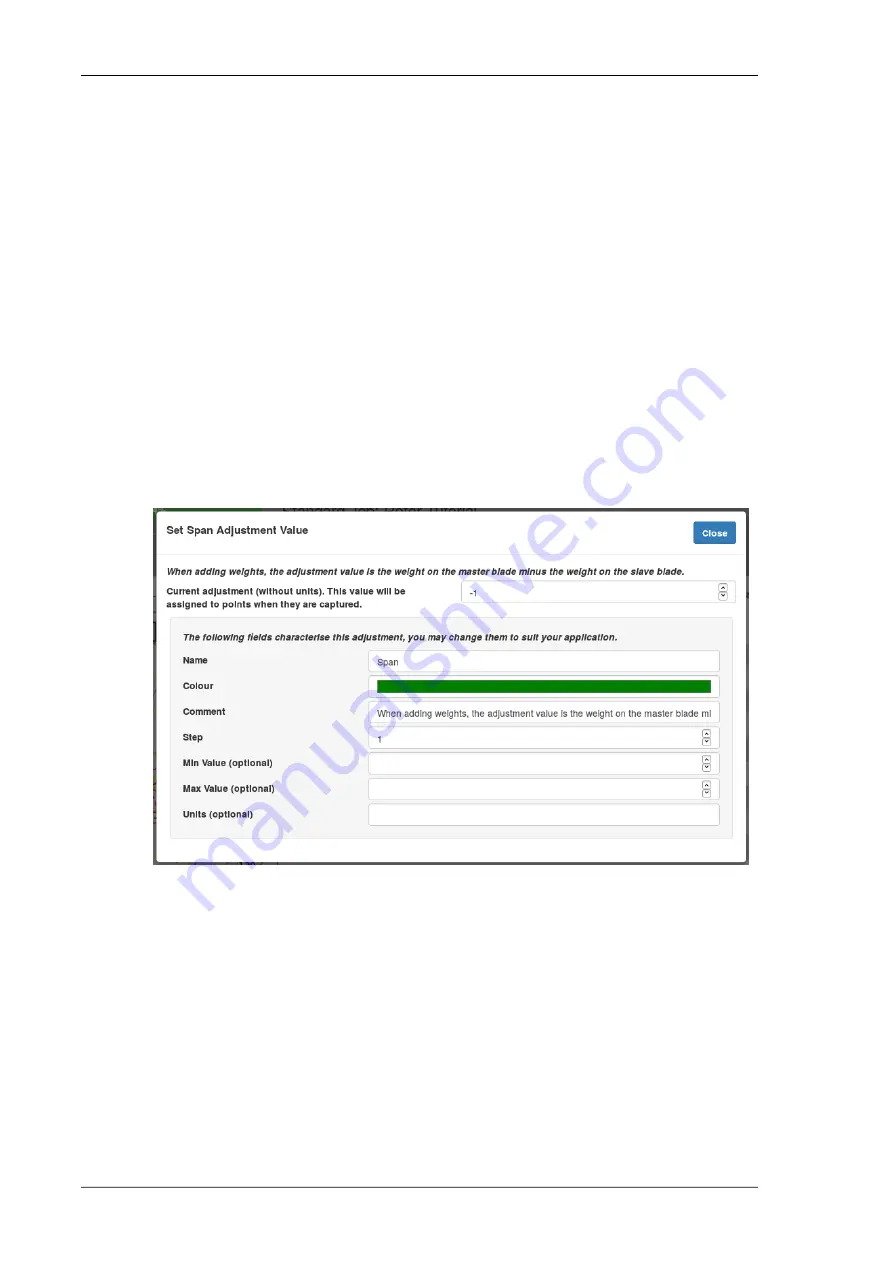
Fig 3.10. Span Adjustment Settings
The adjustment's settings are:
Name
Defaults to
Span, Chord or Pitch. You can change it as
required. The name can be anything so not only can you
change it to a preferred language, you can also change it to
be a completely different concept. The PB-4 simply uses the
adjustment values without any knowledge of what physical
changes those adjustments represent.
www.smartavionics.com
26
Changing adjustment settings
Summary of Contents for PB-4
Page 6: ...www smartavionics com vi...
Page 12: ...www smartavionics com 6...
Page 20: ...www smartavionics com 14...
Page 34: ...www smartavionics com 28...
Page 40: ...www smartavionics com 34...
Page 56: ...www smartavionics com 50...
Page 62: ...www smartavionics com 56...
Page 68: ...www smartavionics com 62...
Page 70: ...www smartavionics com 64...
Page 74: ...www smartavionics com 68...
Page 78: ...www smartavionics com 72...


