C H A P T E R 2
Installing your interactive whiteboard system
12
smarttech.com/kb/170510
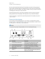
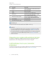
No.
Connector
Connect to:
6
HDMI 2 In
Additional high-definition media (audio and video)
source (not included)
7
Power
Mains power supply
8
USB B
Do not use (for service access only)
9
RJ45 (Cat 5)
Network (for web page management and SNMP
access)
network connection only
10
RJ45 (Cat 5 crossover cable )
Projector 2 (for dual interactive whiteboard
systems)
crossover cable connection only
11
7-pin mini-DIN
ECP cable harness
12
4-pin power-DIN 5V/2A output
ECP cable harness
I M P O R T A N T
The 4-pin mini-DIN 5V/2A output provides power to SMART products only.
N O T E S
l
To connect your SMART Board 685 interactive whiteboard see the
SMART Board 685ix2
interactive whiteboard system installation and cabling guide
).
l
To connect accessories to your interactive whiteboard, refer to the documents included with
the accessories and consult the SMART Support website (
) for
additional information.
Integrating your system with peripheral devices
For information on integrating your SMART Board 685ix2 interactive whiteboard system with
peripheral devices, see
Connecting peripheral sources and outputs
Locking the pen tray to your interactive
whiteboard
To learn how to lock the pen tray to your interactive whiteboard, see the
SMART Board 600 and D600
series interactive whiteboard installation and user’s guide
).


