C H A P T E R 3
Using your interactive whiteboard system
24
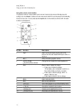
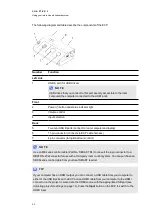
The following diagram and table describe the components of the ECP.
Number
Function
Left side
1
USB A port (for USB drives)
N O T E
USB drives that you connect to this port are only accessible to the room
computer (the computer connected to the USB1 port).
Front
2
Power
button and status indicator light
3
Volume control
4
Input selection
Back
5
Two mini USB B ports (connect to room computer and laptop)
6
11-pin connector (connects to ECP cable harness)
7
4-pin connector (for optional room control)
N O T E
Use an 800 series control cable (Part No. SBX8-CTRL) to convert the 4-pin connector to a
DB9F RS-232 connector for use with a third-party room control system. You can purchase an
SBX8 series control cable from your local SMART reseller.
T I P
If your computer has an HDMI output, you can connect a USB cable from your computer to
either of the USB B ports on the ECP and an HDMI cable from your computer to the HDMI
connector on the projector. Associate the HDMI source with the appropriate USB port (see
on page 14). Press the
Input
button on the ECP to switch to the
HDMI input.
Summary of Contents for 800i6
Page 1: ...SMART Board 800i6 Interactive whiteboard systems Configuration and user s guide ...
Page 2: ......
Page 13: ......
Page 19: ......
Page 39: ......
Page 47: ......
Page 55: ......
Page 105: ......
Page 107: ......
Page 109: ......
Page 113: ......
Page 114: ......
Page 115: ...SMART Technologies smarttech com support smarttech com contactsupport ...


