background image

Appendix A: Specification Drawings

51

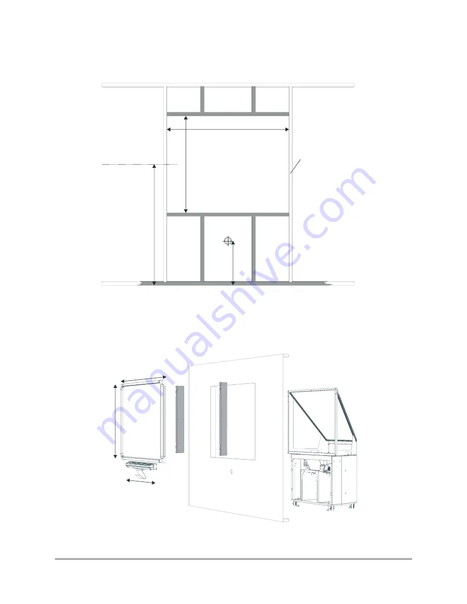
2865 Wall Opening


   46 1/4" 
(117.5 cm)

57 7/8" (147.0 cm)

Minimum

Minimum

The wall opening 
should be 1/4" (0.6 cm) 
larger than the 
suggested minimum to 
accommodate shim 
material and to ensure 
right-angled corners.

Typically, the 
middle of the 
screen is 57 1/2" 
(146.1 cm) from 
the floor.

The wall opening 
must have floor-to-
ceiling vertical studs 
(typically 2" × 4").

NOTE: Support beams 
(highlighted) must be 
sufficiently narrow so that 
their depth plus any wall 
cladding is a maximum of 
3 1/4" (8.3 cm).

Ø 2 3/8" (6.0 cm) 
hole for cables 
(centered below 
the wall opening)

26" (66.0 cm) (based 
on 57 1/2" (146.1 cm) 
distance to the middle 
of the screen)

Wall Opening

Interactive 
Whiteboard

Mounting
Brackets

Wall Opening

Mirror Stand

47

" (1

19.4 

cm)

61 3/8" (155.9

 cm)

38 1/4" (97.2 cm)

Summary of Contents for In-WallRear Projection Interactive Whiteboard

Page 1: ...In WallRear Projection SMART Board TM Installation Guide Interactive Whiteboard...

Page 2: ...r respective owners Copyright Notice 1992 2006 SMART Technologies Inc All rights reserved No part of this publication may be reproduced transmitted transcribed stored in a retrieval system or translat...

Page 3: ...til the marks are removed Don t spray the cleaner directly onto the back of the screen Never under any circumstances apply isopropyl alcohol water or acetone to the back surface of the interactive whi...

Page 4: ...n condensing If possible unplug the unit before thunderstorms However don t touch the unit or the unit s power plug during a thunderstorm as there is a risk of electrical shock Unplug the unit if you...

Page 5: ...ral Instructions for Installing a Projector 25 Installing the MT1065 into the Mirror Stand for the 2865 or 2965 26 Illustrations of Final Cable Connections 28 Making Fine Adjustments to the Projected...

Page 6: ...stance from the Exterior Wall 50 2865 Wall Opening 51 2965 Views 52 2965 Distance from the Exterior Wall 53 2965 Wall Opening 54 Appendix B Restoring the Projector Settings 55 Waste Electrical and Ele...

Page 7: ...ards including the following 1710 66 diagonal 167 6 cm screen 1810 71 diagonal 180 3 cm screen 1910 84 diagonal 213 4 cm screen 2865 71 diagonal 180 3 cm screen with a mirror stand and a projector 296...

Page 8: ...ge 26 The mirror stand is specially designed to project a square image on the screen However you must install the stand a short distance from the back of the interactive screen For the 2865 the maximu...

Page 9: ...yboard kit contents listed below and the pen tray with the wall brackets keyboard brackets and IR receiver attached Inside the accessory kit you ll find a hardware kit containing four hex screws four...

Page 10: ...oftware contains the tools you need to control any computer application and write over it For complete details on this software refer to the SMART Board Software User s Guide that came with your unit...

Page 11: ...es that connect the interactive whiteboard and the pen tray and for the computer cables if the computer is in the projection room However to ensure proper positioning of the cable hole you shouldn t m...

Page 12: ...you must attach the L shaped mounting brackets to both sides of the SMART Board interactive whiteboard The short side of the L the narrow flange attaches to the frame of the interactive whiteboard whi...

Page 13: ...each corner of the frame with the screw hole and keyhole in the bracket 3 Slip each of the four screws through a split lockwasher and then insert them into the appropriate bracket holes at the top and...

Page 14: ...8 Preparing to Install Your Interactive Whiteboard...

Page 15: ...finished the installation For a perfectly flush fit you can make shallow depressions or indentations in the drywall or wallboard material at the edge of the wall opening These indentations will accom...

Page 16: ...sert one screw through the top row of holes in each mounting bracket IMPORTANT Before you install the interactive whiteboard into the wall check that the wall is even If you fit a large interactive wh...

Page 17: ...these cables you must be in the projection room You ll connect the other ends of these cables when you connect the components page 21 You ll find the modular cable and the power supply in the accessor...

Page 18: ...oard 1 Connect one end of the modular cable to the communications hub 2 Connect the power supply cable to the hub To connect the cables Port MOD8 Cable Communications Hub Modular Jack Modular Cable Po...

Page 19: ...r and the eraser You ll also need a Phillips No 2 screwdriver a measuring tool and a level as well as the appropriate tools for creating a wall opening In the following procedure you ll need to insert...

Page 20: ...into each side of the wall opening you just made 5 Using a Phillips No 2 screwdriver insert the drywall anchors into the locations that you marked in step 2 6 Partially insert a screw into the top thr...

Page 21: ...into the mounting bracket underneath the pen tray These screw locations line up with the drywall anchors that you inserted in step 5 12 Ensure the IR receiver is in its slot and run its cable to the c...

Page 22: ...pon which the interactive whiteboard is mounted You ll also need to consider the thickness of your wall when you position the mirror stand When the mirror stand is in place you must align its opening...

Page 23: ...process 1 Wheel the mirror stand into the projection room and remove the cross braces from the screen opening 2 Remove the strap at the front of the mirror stand You ll have to adjust the mirror when...

Page 24: ...ing the leveling legs Raise the mirror stand so that the front opening is the same distance from the top edge of the screen as it is from the bottom edge Depending on your installation the leveling le...

Page 25: ...7 Lock the adjusted leveling leg into place by rotating the remaining jam nut down until it reaches the mirror stand base and then tighten it in place with the wrench 1 Raise the jam nut on the leveli...

Page 26: ...4 Lock the leveling leg in place by tightening the jam nut to the base of the mirror stand Do this by rotating the jam nut downward until it reaches the mirror stand base and then tightening it with...

Page 27: ...eeds power to operate On page 12 you connected one end of the power supply but now you need to connect it to the power cable This cable is in your accessory kit 1 Connect the power cable to the power...

Page 28: ...rojection SMART Board interactive whiteboard comes with a wireless keyboard that includes a trackball mouse as well as an IR receiver and the cable that you connect to your computer Of course you can...

Page 29: ...f this cable when you mounted your pen tray to the wall page 13 NOTE If your serial cable has a power port on the back of the DB9 connector you don t need to use it Power is supplied to the pen tray t...

Page 30: ...onnectors on the cable from the IR receiver to the mouse and keyboard ports on the computer NOTE See page 28 for an illustration of the final cable connections To Infrared Receiver To Pen Tray Mouse C...

Page 31: ...the best image quality match the resolution setting for your computer s display output to the native resolution for your projector Refer to your projector s manual for the optimal resolution of your p...

Page 32: ...Remove the projector from its box turn it over and loosen the three recessed hex screws on the bottom using the M3 hex key in the projector box You ll use these screws to secure the projector to the p...

Page 33: ...ten these screws as you may need to slide the projector slightly forward or backward to adjust the projected image page 30 5 Connect the projector cables as shown 6 Connect the other end of the RGB ca...

Page 34: ...ART USB Adapter Cable Projector SMART Board Interactive Whiteboard Rear View Pen Tray MOD8 Connector DB9 End of SMART USB Adapter Video Cable to Projector Computer Infrared Receiver for Wireless Keybo...

Page 35: ...Cable Projector Pen Tray MOD8 Connector DB9 Connector Computer Video Cable to Projector Infrared Receiver for Wireless Keyboard PS2 Cable to Mouse and Keyboard Ports on Computer To Wall Outlet Power...

Page 36: ...Keystone Image The image adjustments you make depend on your projector Use the following information to adjust the image Remember to use small slow movements until you re satisfied with the image 1 C...

Page 37: ...ally To do this loosen the two large black T knobs located below the projector plate slide the projector plate laterally and then tighten the two T knobs 4 Adjust the image size To do this loosen the...

Page 38: ...osition tighten the thumbscrews NOTE Once the mirror is in position there should be minimal keystone error If there is a significant keystone error re adjust the small mirror to minimize the keystone...

Page 39: ...Press the SMART Board icon in the system tray Windows computers or in the Dock Mac computers and select Control Panel 2 Select SMART Board Settings The SMART Board Settings dialog box appears 3 Select...

Page 40: ...pressing your finger squarely on each cross NOTE If you press on the crosses out of sequence or inaccurately a Bad Orientation Point dialog box appears Use the mouse to click OK because touch awarenes...

Page 41: ...writing or an area of the screen may become unresponsive to your touch Fortunately this problem is easily fixed by performing a simple calibration procedure as described below 1 Press the SMART Board...

Page 42: ...36 Preparing Your Interactive Whiteboard for Use...

Page 43: ...trackball mouse on the keyboard to double click the SMART Board icon on the screen and reconfigure the computer port page 33 1 Close any open computer programs 2 Shut down the computer 3 Put the proje...

Page 44: ...n once the connection to the USB or serial port on the computer is initialized When you pick up a pen tray pen make sure the other pens and the eraser are securely in their pen tray slots Color recogn...

Page 45: ...e you clean the projector unplug it Periodically clean the projector casing with a damp cloth If the projector is heavily soiled use a mild detergent but don t use a strong detergent or a solvent such...

Page 46: ...counting the usage hours for the new lamp 1 Order a replacement standard lamp NEC MT60LP or extended life lamp NEC MT60LPS from your NEC or SMART dealer Don t use any other lamp 2 Access the projecto...

Page 47: ...k behind the interactive screen you ll see two LEDs on the communications hub at the bottom of the screen One LED glows red to indicate that the screen is receiving power The second LED glows green wh...

Page 48: ...42 Using and Maintaining the Interactive Whiteboard...

Page 49: ...Appendix A Specification Drawings 43 Appendix A Specification Drawings NOTE All dimensions within this chapter are 1 8 0 3 cm 1710 Front and Side Views...

Page 50: ...re finished corners Square Finished Wall Opening 27 1 2 69 9 cm based on 57 1 2 146 1 cm to middle of screen Minimum 43 1 4 110 0 cm Minimum 53 7 8 136 8 cm Typically the middle of the screen is 57 1...

Page 51: ...ywall Stud Mounting Bracket 4 5 8 11 8 cm 1 2 5 cm Keyboard IR Receiver Bracket Active Screen Area 56 3 4 W 42 5 8 H 144 2 cm 108 3 cm 4 3 aspect ratio 47 119 4 cm Diagonal 71 180 3 cm 9 5 8 24 4 cm 3...

Page 52: ...uare finished corners Square Finished Wall Opening 26 66 0 cm based on 57 1 2 146 1 cm to middle of screen Minimum 46 1 4 117 5 cm Minimum 57 7 8 147 0 cm Typically the middle of the screen is 57 1 2...

Page 53: ...ud Mounting Bracket Pen Tray attaches to wall Pen Tray 4 5 8 11 8 cm 1 2 5 cm 2 5 8 6 7 cm Keyboard IR Receiver Bracket Active Screen Area 67 1 4 W 50 3 8 H 170 8 cm 128 0 cm 4 3 aspect ratio 55 1 4 1...

Page 54: ...uare finished corners Square Finished Wall Opening 22 55 9 cm based on 57 1 2 146 1 cm to middle of screen Minimum 54 3 8 138 1 cm Minimum 68 5 8 174 3 cm Typically the middle of the screen is 57 1 2...

Page 55: ...ror stand is shown with a 1 2 1 3 cm gap between the casters and the floor The levelling legs have a 1 2 1 3 cm range of adjustment If you adjust these legs make a corresponding adjustment to the heig...

Page 56: ...the wall surface upon which you mount the interactive whiteboard is 3 1 4 8 3 cm If you construct a room to house the mirror stand make it approximately 4 1 2 m deep to provide room for projector main...

Page 57: ...146 1 cm from the floor The wall opening must have floor to ceiling vertical studs typically 2 4 NOTE Support beams highlighted must be sufficiently narrow so that their depth plus any wall cladding i...

Page 58: ...rror stand is shown with a 1 2 1 3 cm gap between the casters and the floor The levelling legs have a 1 2 1 3 cm range of adjustment If you adjust these legs make a corresponding adjustment to the hei...

Page 59: ...or stand and the wall surface upon which the interactive whiteboard is mounted If you construct a room to house the mirror stand make it approximately 5 1 5 m deep to provide room for projector mainte...

Page 60: ...ht angled corners Typically the middle of the screen is 57 1 2 146 1 cm from the floor 22 55 9 cm based on 57 1 2 146 1 cm distance to the middle of the screen 2 3 8 6 0 cm hole for cables centered be...

Page 61: ...gnal Power Management to automatically shut down the projector when no RGB input signal is received from the computer or any other source This helps conserve the life of your projector lamp High Speed...

Page 62: ...56 Appendix B Restoring the Projector Settings...

Page 63: ...its production It may contain hazardous substances By disposing of electrical and electronic equipment appropriately you lower the impact of these substances upon health and the environment and reduc...

Page 64: ...58 Waste Electrical and Electronic Equipment Regulations...

Page 65: ...from Monday to Friday Fax 1 403 806 1256 E mail support smarttech com Website www smarttech com support When you phone Technical Support it will be helpful if you have access to your interactive whit...

Page 66: ...line at www smarttech com registration Sending Feedback You can help us improve our technical documentation by e mailing your comments to TechnicalDocumentation smarttech com Obtaining More Informatio...

Page 67: ...ctor 25 Contacting SMART Technologies 59 D Default Source Select 55 Detect SMART Hardware 33 Distance from the Exterior Wall 2865 50 2965 53 Dual Installation 11 DViT Technology 1 F Fan High Speed Mod...

Page 68: ...Management 55 Projector Cleaning 39 Installation 25 Replacing the Lamp and the Filter 40 Settings 55 Q Quick Orientation 34 R Rear Projection 1 Rear Projection Mode 25 S SMART Board Software 4 SMART B...

Page 69: ...gies Inc 1207 11 Avenue SW Suite 300 Calgary AB T3C 0M5 CANADA Support 1 403 228 5940 or Toll Free 1 866 518 6791 Canada U S Support Fax 1 403 806 1256 support smarttech com www smarttech com 99 00479...

Reviews: