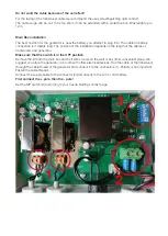
The location of Master Box and Transducers
At the beginning it is necessary to find a suitable place for the
MASTER BOX
location. It is best suited
somewhere in the middle of the boat or in the engine room and in a dry place. We suggest you place the
generator in a room with other electrical devices.
It is necessary to focus on the location of the transducers and the length of the cables. The cables for
the transducers are 8m long, the cable for powering the device is 4m long. The master box must be
connected to the service battery 12 or 24 V system. The battery must be in good condition. We recom-
mend a 150W solar system for constant power supply. The device must be permanently connected to
the voltage.
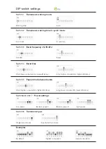
TRANSDUCERS
are mounted according to the type of boat and in the area where the fouling is
stronger.
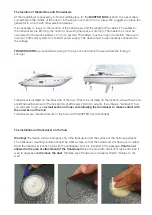
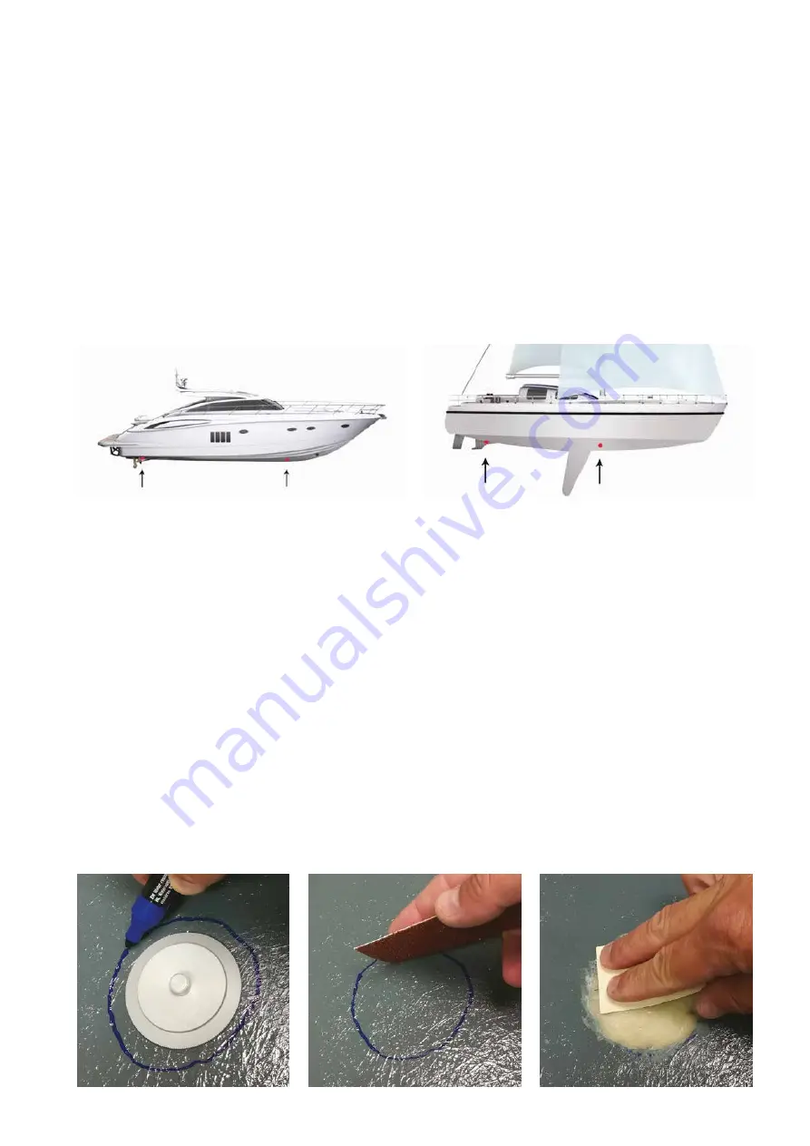
The installation of transducer on the hull.
Warning!
The device will work properly only if the transducer and the surface of the hull fuse perfectly.
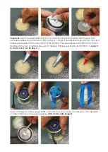
The transducer mounting location should be a flat surface so that the transducer will have good contact.
Sand the transducer location well with the sandpaper, which is included in the package.
Paint is not
allowed in the area of attachment of the transducer!
Wipe the area with an alcohol wipe and clean it
well, to degrease a
nd remove the dust.
Similarly wipe Transducer or Adapter. Wait 5 minutes to dry
well.
Transducer is installed on the inner side of the hull. It has to be installed on the location, where there is no
additional reinforcement of the hull and no shaft bearer 20-30 cm around. If you have a “sandwich” hull,
you will need to remove
a small section of inner core allowing the transducer to make contact with
the outer skin of the hull
.
Transducers are mounted directly to the hull or with ADAPTER (recommended).