background image

Do not wind the cable because of the coil effect!

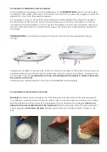
For the laying of the transducer cable we recommend the use self extinguishing rigid conduit.
The cable surge can be cut. If it is too short, it can be extended with a protective box. Max lenght up to 
12m.

Main Box installation

The best position for the generator is near the battery you attempt to plug into. The cable for battery 
connection is 4 meters long. The position of the installation depends on the length of the cables of 
transducers and generator.

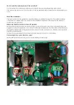
Make sure that the switch is in the OFF position. 

Remove the lid from the main box and fix it with screws on the wall or any other convenient place. We 
suggest you place the generator in a room with other electrical devices. Run the cable of the transducer 
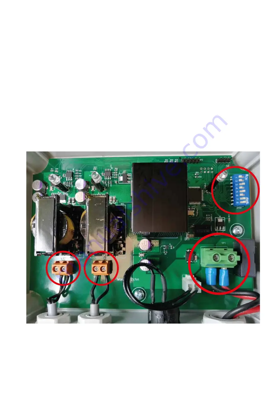
through the cable thread of the generator and connect it to the connectors (1). Polarity is not important. 
Fasten the cable threads.
Connect the supply cable to the connector (2) and directly to the 12V or 24V battery.

First connect the + pole, then the - pole!

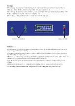
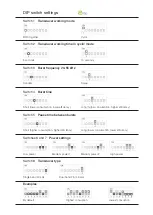
Set the DIP switch (3) according to your needs. Settings on last page.

1

2

3

Summary of Contents for Smart 2 lite

Page 1: ...oys the cells of microorganisms and stops them from adhering to the underwater part of the hull Microorganisms and biofilm are food for algae and seashells that adhere to the hull and underwater parts of a boat such as rudder propeller Ultrasonic antifouling is environmentally friendly Follow the instruction manual and thus correctly install the device The hull of the boat and underwater parts of ...

Page 2: ...e fouling is stronger The installation of transducer on the hull Warning The device will work properly only if the transducer and the surface of the hull fuse perfectly The transducer mounting location should be a flat surface so that the transducer will have good contact Sand the transducer location well with the sandpaper which is included in the package Paint is not allowed in the area of attac...

Page 3: ...sive and pushed hard on the location of the bonding The glue achieves hold within a few minutes Stabilize with a cross of adhesive tape recommended Adhesive reaches its strength after 1h Leave it to dry for min 1h at 20 deg C Apply a thin layer of contact grease OKS11 to the the transducer Screw the transducer onto the adapt er Fasten it tight to remove any air bubbles After 10 min tight it again ...

Page 4: ...epends on the length of the cables of transducers and generator Make sure that the switch is in the OFF position Remove the lid from the main box and fix it with screws on the wall or any other convenient place We suggest you place the generator in a room with other electrical devices Run the cable of the transducer through the cable thread of the generator and connect it to the connectors 1 Polar...

Page 5: ...resolve the problem do not hesitate to contact us on the following e mail address info smart antifouling com sales smart antifouling com www smart antifouling com The warranty period of the device is 5 years upon presenting the copy of the receipt Warnings When voltage drops bellow 11V 12V DC system or 22V 24V DC system Smart 2 lite switches to minimum settings Battery indicator single blink trans...

Page 6: ...tch 8 Transducer type Examples Both together Cyclic 5 seconds 10 seconds Random Swap Long higher consumption higher efficiency Short lower consumption lower efficiency Long lower consumption lower efficiency Short higher consumption higher efficiency Low power Medium power 1 Medium power 2 High power Single band 40 kHz Dual band 25 45 kHz DIP switch settings By default Highest consuption Lowest co...

Reviews: