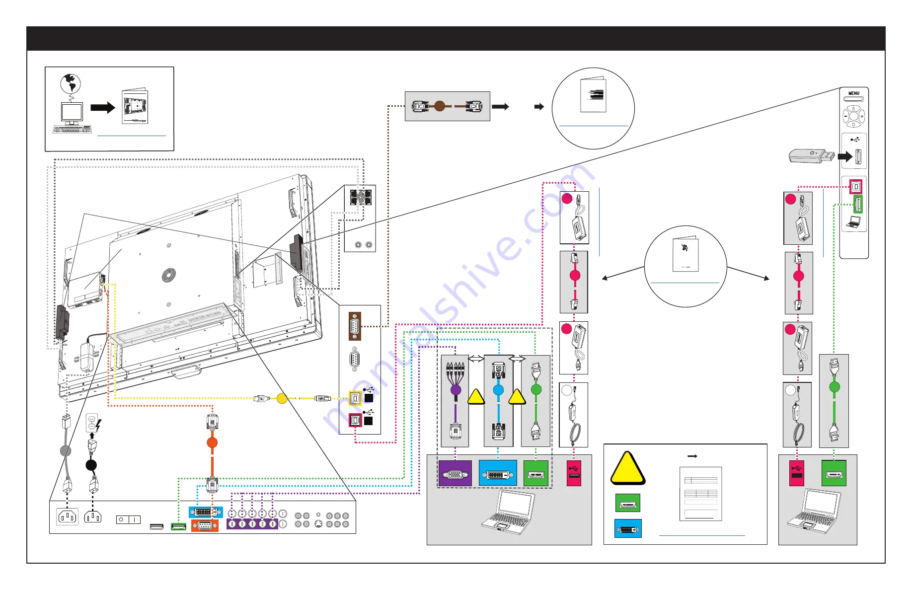
Guest laptop (USB 2)
< 52' (16 m)
f
h
VGA
k
g
f
Remotely managing your
SMART Board™ 8070i
interactive display
Connecting your interactive display to an RS-232 system
2
Connection diagram
2
Serial interface settings
3
Power modes
4
RS-232 programming commands and responses
4
Interpreting the “invalid cmd” response
5
Command inventory
5
Designating video input source commands for a specific video input
6
Designating a target interactive display
7
Commands and controls
8
Power state commands
8
Video input source
9
Video source commands
10
Audio output commands
13
System information commands
14
Service information
18
This document includes detailed instructions on how to set up your computer or room control system
to remotely manage your SMART Board™8070i interactive display using an RS-232 serial interface.
1
USB 2 HDMI/DVI
Copyright SMART Technologies. All Rights Reserved.Header
Configuring the video and touch input for your SMART Board 8070i interactive display
Overview
You can connect your
SMART Board
8070i
interactive display
to up to three computers at once. Each computer must be connected to the
interactive
display
with a USB cable for touch input and a video cable for video input.
The following table shows the default touch input and video input pairings.
If you want to use a video and touch input pairing other than the default, you can change the video input settings in the
Video and Touch Input Settings
window of the SMART control panel.
N O T E
If multiple
interactive displays
are connected to your room computer, disconnect all but one of the
interactive displays
, and then configure the
interactive
displays
one at a time.
Details
SMART hardware
SMART Board
8070i
interactive displays
SMART software
SMART Notebook
10.8 SP1
collaborative learning software
,
SMART Meeting Pro
2.3
software
and SMART
Product Drivers 10.8
Operating systems
Windows operating systems and Mac OS operating system software
Computer
Touch input connection
Default video input connection
Room computer
USB 1
VGA
Guest laptop
USB 2
RGB/HV
Side laptop
USB 3
HDMI 2
Using the computer that’s connected to the USB 1 connection, configure the video input for each touch input connection using the
Video and Touch Input
Settings
window.
I M P O R T A N T
You must have the latest version of
SMART Notebook
software or SMART Meeting Pro software installed on the computer connected to USB 1.
The
interactive display
status light must be green or flashing green.
The interactive display cannot be in Eco-Standby mode.
Page 1 of 3
Configuring the video and touch input for your SMART Board 8070i interactive display (...
2/5/2012
http://www.smarttech.com/us/Support/Support/Documents/KB4/170065.a...
DVI
HDMI
DVI
HDMI
j
m
OR
OR
1
Extending
USB Connections
SMART Board® 800 series interactive
whiteboards and systems
Room
control
n
Bottom connection panel
Speakers
1
2
Inside
connection
panel
c
e
Guest laptop (USB 3)
The USB drive connects
to the appliance.
Side laptop
connection panel
< 52' (16 m)
h
HDMI
j
p
q
p
a
Audio
connection
panel
Appliance
SBID 8070ie-MP appliance
For cautions, warnings and other important product information see
Important information for your
SMART Board™ interactive display
(
).
1
2
b
a
Alternative cable connections


