background image

packaging from your authorized SMART reseller (

smarttech.com/where

).

l

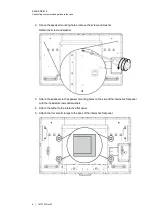
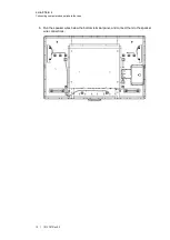
Attach the speakers and connect the speaker wires to the interactive flat panel before

you wall-mount it. For more information, see

Installing the speakers

on page 8.

Important mounting considerations for trained installers

Consider the following when mounting the interactive flat panel on a wall:

l

l

Plan your workflow to include cabling because some cable connection points might not be

accessible after installation.

l

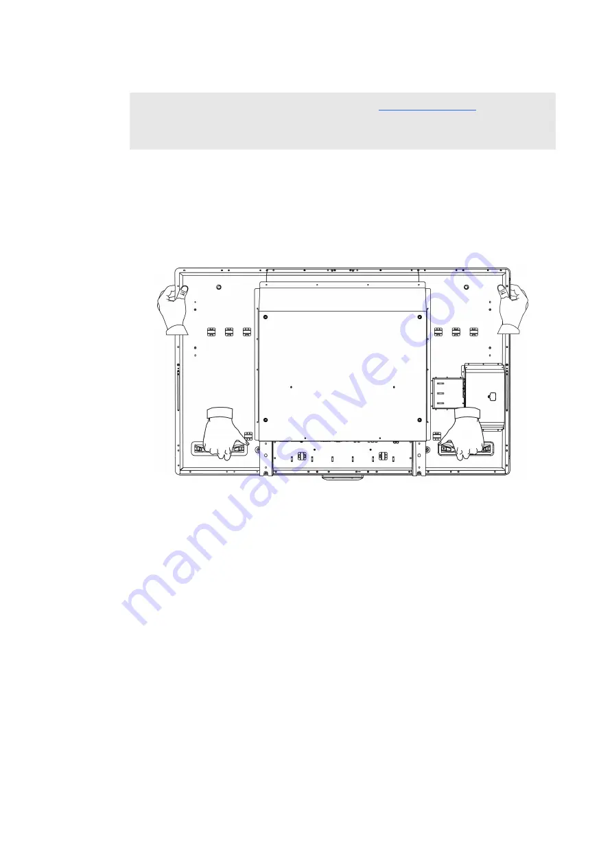
Carry and lift the interactive flat panel by gripping the handles and sides.

l

To mount the interactive flat panel on a wall, you require a standard VESA 600 mm × 400

mm compatible wall mount bracket (not included). The wall mount bracket must have

minimum depth of 14 mm to ensure sufficient space for the speakers.

l

Use M8 screws to fasten the wall bracket. The screws must be 14–15 mm long plus the

thickness of the bracket and the washer.

l

The recommended fasten force is 99.57–121.70 in-lb. (11.25–13.75 N·m).

l

Refer to the instructions included with the mounting equipment for more detailed

information.

C H A P T E R 1

Installing your interactive flat panel

5     |     1013787 Rev 03

Summary of Contents for 8055i

Page 1: ...SMART Board 8055i and 8055i SMP Interactive flat panel Installation guide...

Page 2: ...case the user will be required to correct the interference at his own expense Trademark notice SMART Board SMART Notebook SMART Meeting Pro SMART GoWire smarttech the SMART logo and all SMART tagline...

Page 3: ...o your interactive flat panel 12 Connecting peripheral devices to your interactive flat panel 17 Chapter 3 Installing SMART software 19 Installing SMART Meeting Pro software 20 Using a SMART GoWire ca...

Page 4: ......

Page 5: ...eed a team of professional installers to install your SMART Board 8055i interactive flat panel This chapter provides additional considerations and details for installing your interactive flat panel I...

Page 6: ...nder SMART Board 8055i SMP and 8055ie SMP interactive flat panels only l SMART Notebook collaborative learning software DVD SMART Board 8055i interactive flat panels only Documentation l Installation...

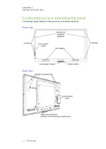
Page 7: ...nents of your interactive flat panel The following images identify the components of your interactive flat panel Front view Back view C H A P T E R 1 Installing your interactive flat panel 3 1013787 R...

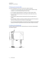
Page 8: ...local building codes to ensure your installation area can support this weight C A U TI ON Do not allow the weight of the interactive flat panel to rest on the color select module because it is not de...

Page 9: ...lation l Carry and lift the interactive flat panel by gripping the handles and sides l To mount the interactive flat panel on a wall you require a standard VESA 600 mm 400 mm compatible wall mount bra...

Page 10: ...l Do not install the interactive flat panel near where the main power supply enters the building l Ensure adequate ventilation or provide air conditioning around the interactive flat panel so that he...

Page 11: ...14 Connecting a guest laptop 15 Connecting peripheral devices to your interactive flat panel 17 Bottom terminal panel 17 This chapter includes information on connecting your interactive flat panel to...

Page 12: ...g the speakers Your interactive flat panel comes with two 15 W speakers g To install the speakers 1 Attach the tether to the speaker C H A P T E R 2 Connecting computers and peripheral devices 8 10137...

Page 13: ...s to the speaker mounting holes on the side of the interactive flat panel with the included screws and washers 4 Attach the tether to the interactive flat panel 5 Attach the four small clamps to the b...

Page 14: ...6 Run the speaker wires below the bottom terminal panel and connect them to the speaker wire connections C H A P T E R 2 Connecting computers and peripheral devices 10 1013787 Rev 03...

Page 15: ...de terminal panel of the interactive flat panel to the serial output on your computer or room control system I MP OR TA N T Do not use a null modem cable Use only a standard RS 232 cable For more info...

Page 16: ...2 connector N OTE This document describes the default USB and video connections To customize the USB and video mapping see Configuring the video and touch input for your SMART Board 8055i interactive...

Page 17: ...t 4 Connect the power cable from your computer to a power outlet 5 Turn on your computer 6 Turn on the main power switch on the bottom terminal panel and then press the Power button on the front contr...

Page 18: ...er 2 connection location W A R N I N G Ensure that any cables extending across the floor to your SMART product are properly bundled and marked to avoid a trip hazard g To set up a computer 2 connectio...

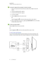
Page 19: ...e is VGA 2 6 Select the USB audio input source by pressing the AUDIO INPUT button on the remote control until the source is USB g To return to using computer 1 Press the VGA 1 button on the remote con...

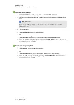
Page 20: ...mote control OR Press the Input button on the front control panel until the source is HDMI 2 5 Select the HDMI audio input source by pressing the AUDIO INPUT button on the remote control until the sou...

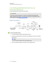
Page 21: ...oduct FRU Appliance SB8 smarttech com kb 170062 Bottom terminal panel g To connect a peripheral device 1 Turn off the interactive flat panel and the peripheral device 2 Connect the peripheral device s...

Page 22: ......

Page 23: ...5i SMP interactive flat panels also include a SMART GoWire auto launch cable that provides the features of SMART Meeting Pro software without installing the software on your computer For more informat...

Page 24: ...Check for Updates and Activation The SMART Product Update window appears 4 Follow the on screen instructions to update your SMART Meeting Pro software to the latest version Using a SMART GoWire cable...

Page 25: ...teractive flat panel and can use SMART Meeting Pro software while your laptop is connected to your interactive flat panel g To disconnect a SMART GoWire cable 1 If required save your SMART Meeting Pro...

Page 26: ...version Updating SMART Product Drivers To use touch control and digital ink on your interactive flat panel you require SMART Product Drivers 11 or later on your computer g To update SMART Product Driv...

Page 27: ...bstances RoHS directive This product meets the requirements of the European Union s Restriction of Certain Hazardous Substances RoHS directive 2011 65 EU Consequently this product also complies with o...

Page 28: ......

Page 29: ......

Page 30: ......

Page 31: ......

Page 32: ...SMART Technologies smarttech com support smarttech com contactsupport 1013787 Rev 03 1013787...

Reviews:

Related manuals for 8055i