Copyright 1998 by SMART Devices Inc.
5945 Peachtree Corners East
Norcross, GA 30071-1337
Table of Contents
AFT660 AFTERBURNER
SECTION 1
INTRODUCTION
.......................... 2
SECTION 2
INSTALLATION .................................... 3
SECTION 3
OPERATING INSTRUCTIONS
....... 4
SECTION 5
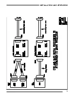
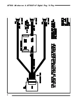
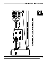
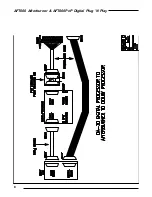
HOOK-UP DIAGRAMS
................. 5
SECTION 6
SCHEMATICS
.................................... 10
AFT660PnP AFTERBURNER W/ DIGITAL PLUG 'N PLAY
SECTION 7
INTRODUCTION
.......................... 14
SECTION 8
INSTALLATION .................................... 15
SECTION 9
OPERATING INSTRUCTIONS
....... 17
SECTION 10
SCHEMATICS
................................... 18
LIMITED WARRANTY: SMART products and accessories are warranted against malfunction or failure due to de-
fects in workmanship or materials for a period of one year from the date of shipment. If a problem occurs during the
warranty period, the unit will be repaired, or replaced at our option, without charge for materials or labor. If air freight
is requested by the dealer, the difference between air and surface charges will be billed to the dealer. This limited
warranty does not cover products that have been abused, altered, modified, or operated in other than specified condi-
tions. Prior factory approval is required on all returns. Returned equipment or defective parts must be shipped
freight prepaid to us by the dealer or customer.
Our limited warranty does not cover damages resulting from accident, misuse or abuse, lack of responsible care, or
failures not attributable to manufacturing defects, except as provided herein. SMART Devices, Inc. makes no war-
ranties, express or implied, including warranties of merchantability or fitness for a particular purpose.
RETURN POLICY: Factory authorization MUST be obtained before returning any product. A 15% restocking charge
will be issued on unused equipment (in original box) that is returned for credit. Credit is issued to the dealers ac-
count. The credit may be used against future purchases and no cash transactions are offered. All returns must be
shipped freight prepaid by the dealer. Equipment returned without a factory RA (Return Authorization) will be re-
fused.
SMART products are designed to deliver unsurpassed quality in workmanship and performance. The
following information gives detailed instructions on the installation and operation of the SMART AFT660
processor. We strongly encourage new owners of the AFT660 to thoroughly read this entire manual be-
fore placing their new SMART product into service. This will ensure that the AFT660 will be operated
properly to give the superior performance that it was designed to deliver.
For service or installation assistance, please call our
Technical Support Department between the hours of
8 a.m-5 p.m. E.S.T., Mon.-Fri.
1-800-45-SMART


