11
INSTALLATION AND OPERATION
Sony SDDS
Audio Signals: Left, Center, Right, Left Surround, Right
Surround, and Subwoofer.
Control Signals: Digital and Optical (See Below).
EXTRA Signals: PROJ1, PROJ2, MUTE, LEFT EXTRA,
and RIGHT EXTRA.
Because of the unusual topography of the Sony SDDS
system, the AFTPnP uses some special circuitry to
generate the necessary control signals. The SDDS’
DATA PRESENT and MANUAL BYPASS signals are used
to pulse the Digital and Optical control lines at appro-
priate times. The Optical signal can be applied to SR or
A when used with MOD6, or SR/A when used with
MOD2.
SECTION 3
Installation
The Afterburner Digital Plug ‘N Play fits into a 3.5” rack
space (2 standard rack units).
1. Mount the unit in a rack location close to the
processor and at a height that is convenient for plugging
from the mobile digital player cart.
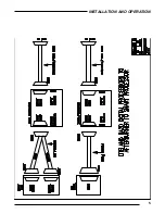
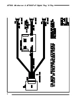
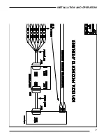
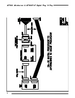
2. Connect the AFTPnP to the specific processor as
follows:
SMART MOD IIC, IV, V, and VI: Using a standard 25
Pin D-Type female to male cable, connect the AUDIO
OUT DB25 port on the back of the Afterburner chassis
to the DIGITAL INPUT/INTERFACE port of the SMART
processor.
OTHER PROCESSORS: A special cable can be con-
structed for other processors using the AUDIO OUT
Pinouts provided on page 4, and the input pinouts
provided in your processor's manual.
3. Set the Optical Format Jumpers (H4, H5, & H6) on
the back of the Plug 'N Play main board according to
the following configurations (also see the diagram to
the right):
a) DTS-6D to MOD VI: No jumpers are necessary.
Make sure that H4, H5 and H6 header pins have no
jumpers across any two pins (hang them off one pin if
any are present). H5 and H6 can be used to "force" the
DTS-6D to default to either A or SR by applying jumpers
across the top two pins for SR or bottom two pins for A
on each set of headers.
b) DTS-6D to MODIIB, IIC, IV, V, Dolby CP65, and
other processors: Put jumpers on the top two pins of the
FORCE headers (H5 & H6) so that SR mode is forced on
the Digital player. No jumper is needed on H4.
c) DTS-6, Sony SDDS and Dolby DA-20 to MOD VI: Set
the H4 jumper to SR or A (top two or bottom two pins,
respectively) depending on the format of the optical
backup of the specific film you are presenting. No
jumpers are needed on H5 and H6.
d) DTS-6, Sony SDDS and Dolby DA-20 to other
processors: Set the H4 jumper to SR (top two pins). The
default format for the specific film must be set in the
processor.
4. For systems using the optional Digital Plug 'N Play
Rover Panel:
a) Mount the Rover Panel in the mobile digital player
rack. (The Rover Panel fits into a standard 1.75" (1 rack
unit) space.
b) Attach one DB25 cable to Audio output of the DA-20
or DTS-6D digital player.
c) Attach one DB25 cable to the Control or Automation
output of the DA-20 or DTS-6D digital player.
d) Attach the DB9 cable to the Soundhead output of the
DA-20 or DTS-6D digital player.
e) Attach the three DB cables to the Rover Panel in the
A
H5
H6
SR
H4
A
SR
A
SR
a
b
c
d
c
SR
A
Optical mode jumper settings
The settings a, b, c SR, c A, and d are explained in
the above paragraphs.


