12
AFT660 Afterburner & AFT660PnP Digital Plug 'N Play
appropriate holes (labeled SIGNAL, CONTROL, and
SOUNDHEAD on the front) from the backside. Secure
with provided nuts.
5. Connect the digital player to the Digital Plug 'N
Play:
Note: NEVER PLUG TWO DIGITAL SYSTEMS IN AT
THE SAME TIME.
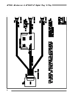
DTS-6: Use the cable provided by Dolby (DB50 to 2 20
pin and 1 10 pin header connectors. Connect from the
J1 50 pin connector on the back of the DTS-6 to the
DTS-6 SIGNAL and CONTROL ports on the front of the
Plug 'N Play. The JM21 20 pin connector is the SIG-
NAL, and the BS22 10 pin connector is the CONTROL.
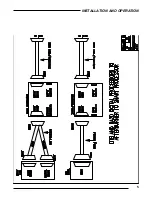
Important Note: When connected to the Plug 'N Play,
the SIGNAL cable (JM-21) exits the connector upwards,
and the CONTROL cable (BS-22) exits downward. (see
photo on opposite page)
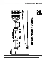
DTS-6D: Use two DB25 cables. Connect from the
ANALOG OUT and AUTOMATION ports on the back of
the DTS-6D (or the SIGNAL and CONTROL ports on the
Rover Panel) to the SIGNAL and CONTROL ports on the
front of the Plug 'N Play, respectively.
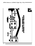
DA-20: Use two DB25 cables. Connect from the back
of the digital player (or the front of the Rover Panel) to
the SIGNAL and CONTROL ports on the front of the
Plug 'N Play.
SDDS: Use 1 DB37 and 1 DB25 cable. Connect from
the back of the SDDS to the SDDS SIGNAL and CON-
TROL ports on the front of the Plug 'N Play.
6. If desired, connect the EXTRA CONTROLS. The
EXTRA CONTROLS connector is a DB25 plug which
carries the extra signals described in the
Specific
Digital Player Features section. A special cable may
be created for the purpose of feeding through these
extra signals into the rack unit as desired. The EXTRA
CONTROLS pinouts are as follows:
Pin 1: PROJ1MOTORA (DTS-6D)
Pin 2: PROJ1DOUSERA (DTS-6D)
Pin 3: PROJ2MOTORA (DTS-6D)
Pin 4: PROJ2DOUSERA (DTS-6D)
Pin 5: PROJ1MOTORB (DTS-6D)
Pin 6: PROJ1DOUSERB (DTS-6D)
Pin 7: PROJ2MOTORB (DTS-6D)
Pin 8: PROJ2DOUSERB (DTS-6D)
Pin 10: MUTE (SDDS)
Pin 11: PROJ1 (DTS-6, SDDS)
Pin 12: PROJ2 (DTS-6, SDDS)
Pin 13: GO (DTS-6)
Pin 19: MONOSURR (DTS-6, DTS-6D)
Pin 20: LEFT EXTRA (DTS-6D, SDDS)
Pin 21: RIGHT EXTRA (DTS-6D, SDDS)
Pin 25: COM (ALL)
See the manual for the related digital player for an
explanation of these signals.
7. Connect digital player to digital soundhead.
8. Plug Afterburner power cord into rack power strip.
9. Plug digital player's power cord into rack power
strip.
10. Follow the instructions in the Afterburner 660
section of this manual for calibrating the Afterburner
system (SECTION 2: INSTALLATION).


