13
INSTALLATION AND OPERATION
SECTION 9
Operating Instructions
Red Bypass/Power Switch
This switch located on the front panel applies power to
the unit and routes the audio channels through the cir-
cuitry in the AFT660. In the event that the AFT660 has
failed, this switch can be turned off which will force the
audio channels to be “hard bypassed” around the
AFT660. The Power Switch must be on for the Plug 'N
Play interface to operate. To use the Plug 'N Play with-
out the Afterburner effect, leave the power on and dis-
engage the Afterburner using the Engage button.
Engage Button
This button on the front panel turns the compression cir-
cuitry on and off in the AFT660. When the red LED on
the button is illuminated, the compression circuitry is
activated. This is the normal power-up state for the
AFT660. The Engage button has no effect on the Plug
'N Play circuitry.
Processing LED
When this LED on the front panel illuminates, the audio
level coming into the AFT660 has surpassed the thresh-
old level, and the compression action on the high end
of the audio material is taking place. This LED should
only illuminate on hard or loud passages. If it is never
illuminating or is on all the time, then the threshold lev-
els may not be set properly (see Installation Instruc-
tions). This LED will illuminate whenever the
Subwoofer or one of the five main channels (Left, Cen-
ter, Right, Left Surround or Right Surround) exceeds the
threshold level.
Digital Interfaces
Make sure that the Digital Plug 'N Play has been prop-
erly configured for use with the specific digital player
being used (see the Installation Instructions). Plug the
Signal and Control cables into the appropriate ports on
the front of the Plug 'N Play and on the mobile digital
player rack.
NEVER PLUG TWO DIGITAL PLAYERS IN
AT THE SAME PLUG 'N PLAY AT THE SAME TIME!
EQUIPMENT FAILURE MAY RESULT!
Things to watch for:
The DA-20's connectors are identical. Make sure that
the correct cable is plugged into the correct port.
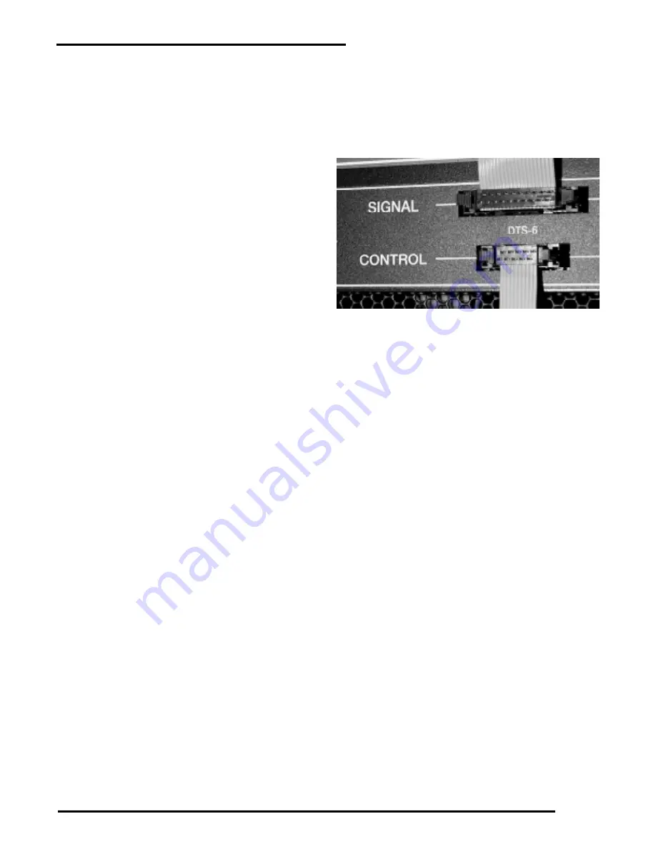
The DTS-6's connectors plug in so that the top
connector's cable goes up (SIGNAL), and the bottom
connector's cable goes down (CONTROL). See the
photo to the right.
If the digital player is not reverting to the correct opti-
cal mode during times of digital data failure, or is not
reverting at all, refer to step 3 of the Plug 'N Play Instal-
lation instructions for proper jumper settings.
Proper orientation for DTS-6 cables.


