3
INSTALLATION AND OPERATION
A large button on the front of the product allows the op-
erator to select the mode of operation. If the digital
soundtrack you receive is well recorded and well bal-
anced, then do nothing. The signals will pass through
the AFT660 without being altered. However, if you re-
ceive a screamer, the operator can push the ENABLE
button and the automatic level control kicks in. No spe-
cial training of the staff is required.
Installation
Inputs and Outputs
The output of the digital decorder should feed directly
into the input of the AFT660 for the unit to operate
properly. However, if desired, the AFT660 can be in-
stalled after the processor so that the AFT660 can moni-
tor the levels of both optical and digital prints using the
Afterburner Breakout board (Part #0660A390). See the
Afterburner Breakout board section of the Setting the
Threshold Levels instructions.
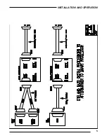
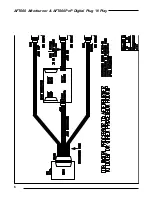
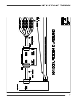
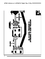
See section 5 for configuration diagrams for various
types of systems.
If the AFT660 is installed into an existing digital sound
system, it will not effect any calibration settings that
were made previously. Only the threshold levels of the
AFT660 need to be adjusted.
The AFT660 has two inputs, both of which are con-
nected together in parallel. One input is a female DB25
connector, and the other is a header pin connector.
Both will accept the outputs of any six channel digital
decoder. Only one input will be used and the choice
will depend on the other equipment used (see hookup
diagrams). Smart offers adapter cables to mate any
digital decoder to the AFT660. See the illustrations at
the end of the manual for specific hookup instructions.
The AFT660 has two outputs, both of which are con-
nected together in parallel. One output is a male DB25
connector, and the other is a header pin connector.
Only one output will be used. The output from the
AFT660 will mate with the rest of the sound system. On
SMART processors, this will be the digital inputs on the
processor. See the illustrations at the end of the manual
for specific hookup instructions.
Setting The Threshold Levels
There are two threshold levels on the AFT660 that need
to be set after hooking the unit into the sound system.
One is the threshold level for the five main channels
(Left, Center, Right, Left Surround & Right Surround).
The other is the threshold level for the Subwoofer chan-
nel. The threshold level trimpots are located at the rear
of the unit. Two single-turn pots allow the user to set
the threshold level. Turning the pot clockwise in-
creases the threshold level. In other words, a louder
sound passage is required to reach the threshold level.
Turning the pot counterclockwise has the reverse effect.
Once a sound passage exceeds the threshold level, the
AFT660 compresses the audio above the threshold level
at a 2:1 ratio. This means that for every 2 dB increase in
sound pressure level above the threshold, the AFT660
allows only a 1 dB increase. The instructions below
will outline a procedure for setting the threshold level
at what we believe is an optimum setting. However, the
end user is free to lower or raise the threshold level from
this setting to accommodate their particular situation.
DTS:
The DTS digital decoder is supplied with a test
disc titled “DTS 6-track Setup Disc.” This disc is a con-
venient item for setting the AFT660 threshold levels.
The test disc has 50 tracks with different test signals for
the various channels. One test is “Pink Noise @ Refer-
ence Level (85 dB SPL).” The Left, Center and Right
channels have different tracks for this test:
Track #37 — Left Pink Noise @ Reference Level
(85 dB SPL)
Track #39 — Center Pink Noise @ Reference Level
(85 dB SPL)
Track #41 — Right Pink Noise @ Reference Level
(85 dB SPL)
Put the test disc in the DTS and adjust the rotary dials
for track #37. This is the Left channel pink noise test.
Make sure that the engage light on the front of the
AFT660 is on, indicating that the AFT660 is “active.” If
not, then press the Engage button to activate the
AFT660 (the light on the Engage button will illuminate).
With the Pink Noise playing, adjust the MAIN thresh-
old control until the red LED just above the pot illumi-
nates. Turn the rotary dials on the DTS for both Center
and Right Pink Noise (see above). Make certain that the
LED above the threshold pot illuminates while these
channels are playing Pink Noise. Make any minor ad-
justment to the MAIN threshold pot so that all three
tests illuminate the red LED
Adjusting Subwoofer threshold level: Set the rotary di-
als on the DTS to track #42. This is Sub-Bass Pink
Noise @ Reference Level (85 dB SPL). With the Pink
Noise playing, adjust the SUB threshold control until
the red LED just above the pot illuminates.
These adjustments set the AFT660 to activate its 2:1
compression when the sound pressure level in the au-
ditorium reaches 85 dB. As stated before, the end user
may wish to set the threshold level to a higher or lower


