4
AFT660 Afterburner & AFT660PnP Digital Plug 'N Play
setting depending on their requirements.
Other Digital Decoders:
If there is a pink noise source available for the system,
play it through the Left channel. Set the system so that
85 dB SPL is measured in the auditorium while the Af-
terburner is DISENGAGED. Engage the Afterburner,
and adjust the MAIN threshold level so that the red
LED just about the pot just comeson. Confirm that the
LED stays on when pink noise is played through Cen-
ter and Right channels also.
Play the pink noise through the subwoofer channel at
85 dB SPL in the auditorium, again engage the After-
burner and set the SUB threshold level so that the red
LED just above the pot just stays on.
If no calibration sound material is available, then set-
ting the threshold levels for other digital decoders will
require playing a digital print and setting the threshold
levels by ear. Wait for a sound passage that has some
strong dialog. Set the MAIN threshold level so that the
red LED just above the pot blinks during these pas-
sages. Verify that during loud action scenes the red
LED illuminates. For the SUB threshold adjustment,
wait for a sound passage with a strong amount of
subwoofer material. Adjust the SUB threshold level so
that the red LED above the pot just illuminates.
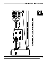
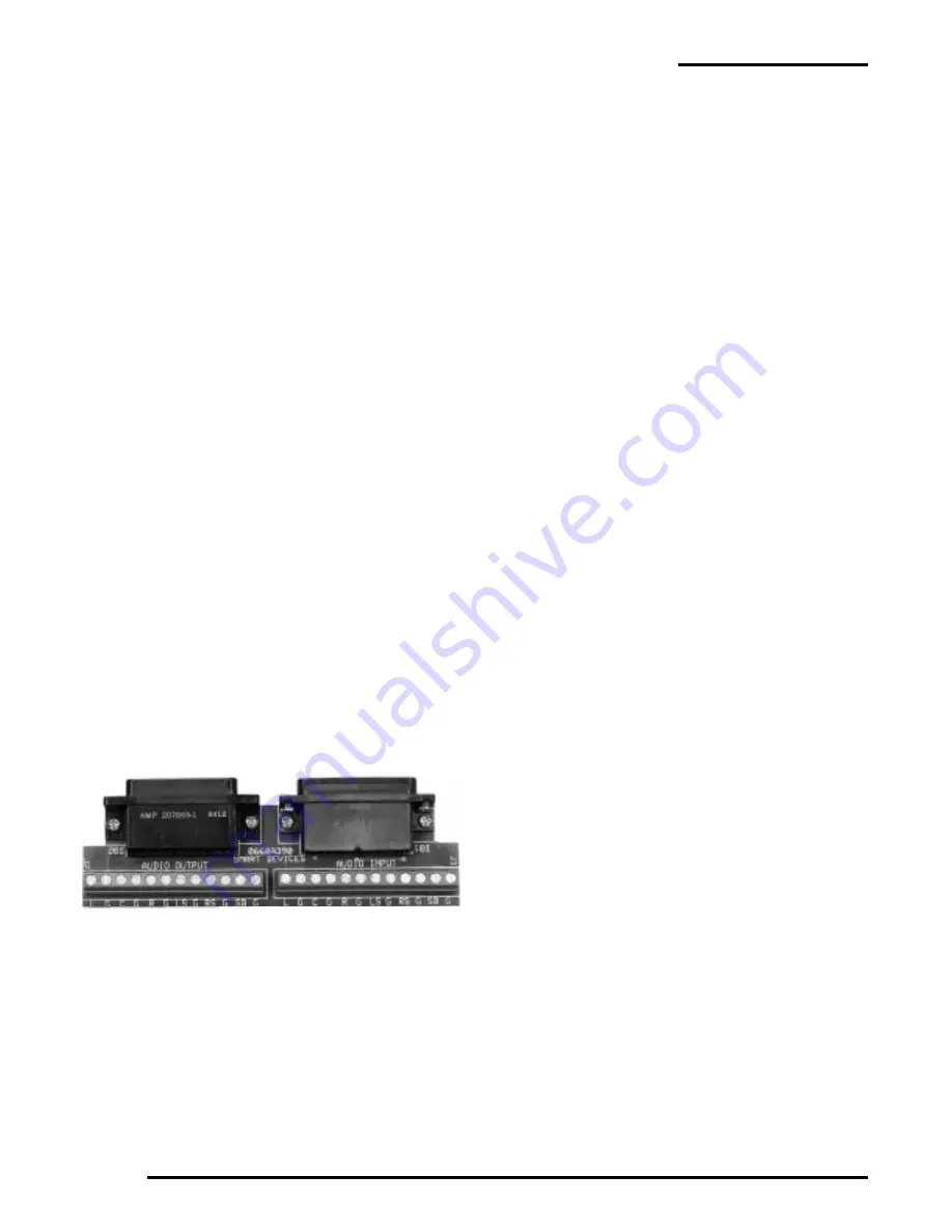
Using the Afterburner Breakout board:
When using the Afterburner AFTER a processor to com-
press optical and digital soundtracks, it is possible to
set the thresholds using either a digital OR optical Pink
Noise track, and then following the instructions in the
Other Digital Decoders section above.
Note: When either of the red LED’s above the threshold
pots illuminate, the red PROCESSING LED on the front
of the AFT660 will also illuminate, indicating that the
AFT660 is compressing the top end of the sound mate-
rial.
Operating Instructions
Red Bypass/Power Switch
This switch located on the front panel applies power to
the unit and routes the audio channels through the cir-
Pinout Configuration
Input DB25:
Input Header:
Left: Pin 1
Left: Pin 2
Center: Pin 3
Center: Pin 14
Right: Pin 5
Right: Pin 8
Left Surround: Pin 6
Left Surround: Pin 4
Right Surround: Pin 7
Right Surround: Pin 3
Subwoofer: Pin 8
Subwoofer: Pin 10
GND: Pin 14-25
GND: Pin 1
Mono: Pin 9
Mono: Pin 19
Music: Pin 10
Music: Pin 13
Stereo A: Pin 11
Stereo A: Pin 20
Digital: Pin 12
Digital: Pin 18
SR/Optical: Pin 13
SR/Optical: Pin 17
-15 VDC: Pin 11
+15 VDC: Pin 12
Output DB25:
Output Header:
Left: Pin 1
Left: Pin 2
Center: Pin 3
Center: Pin 14
Right: Pin 5
Right: Pin 8
Left Surround: Pin 6
Left Surround: Pin 4
Right Surround: Pin 7
Right Surround: Pin 3
Subwoofer: Pin 8
Subwoofer: Pin 10
GND: Pin 14-25
Mono: Pin 9
Music: Pin 10
Stereo A: Pin 11
Digital: Pin 12
SR/Optical: Pin 13
cuitry in the AFT660. In the event that the AFT660 has
failed, this switch can be turned off which will force the
audio channels to be “hard bypassed” around the
AFT660.
Engage Button
This button on the front panel turns the compression
circuitry on and off in the AFT660. When the red LED
on the button is illuminated, the compression circuitry
is activated. This is the normal power-up state for the
AFT660.
Processing LED
When this LED on the front panel illuminates, the au-
dio level coming into the AFT660 has surpassed the
threshold level, and the compression action on the high
end of the audio material is taking place. This LED
should only illuminate on hard or loud passages. If it is
never illuminating or is on all the time, then the thresh-
old levels may not be set properly (see Installation In-
structions). This LED will illuminate whenever the
Subwoofer or one of the five main channels (Left, Cen-
ter, Right, Left Surround or Right Surround) exceeds the
threshold level.


