User Manual - twentynine
3.1
Gigabit Ethernet Interface (GCC)
The Ethernet Interface provides configuration access to the camera and is also used for image data
transmission. The connector is a standardize RJ45 jack, assigned like shown in Table 11 below.
Ethernet Connector Type
RJ45, Ethernet 1000BaseT, 802.3 compliant
Pin no.
Signal
Description
1
BI_DA+
Bi-directional pair +A
2
BI_DA-
Bi-directional pair -A
3
BI_DB+
Bi-directional pair +B
4
BI_DC+
Bi-directional pair +C
5
BI_DC-
Bi-directional pair -C
6
BI_DB-
Bi-directional pair -B
7
BI_DD+
Bi-directional pair +D
8
BI_DD-
Bi-directional pair -D
Table 11: Ethernet connector type and assignment
3.1.1
Cabling Requirements
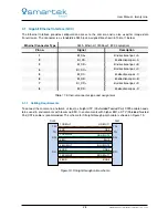
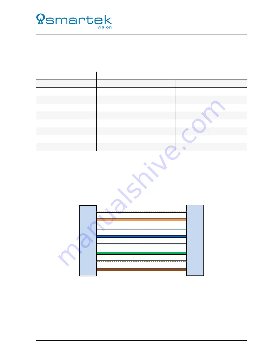
To connect the camera to a network, at least a straight UTP (Unshielded Twisted Pair) CAT5e cable needs
to be used in environments with low or no EMI. In environments with higher EMI, a STP (Shielded Twisted
Pair) CAT6 cable is recommended. The scheme for Straight-through patch cable is shown on Figure 19.
RJ45
RJ45
TD+
TD-
RD+
RD-
TD+
TD-
RD+
RD-
1 OR/WHT
2 OR
3 GRN/WHT
4 BLU
5 BLU/WHT
6 GRN
7 BRN/WHT
8 BRN
OR/WHT 1
OR 2
GRN/WHT 3
BLU 4
BLU/WHT 5
GRN 6
BRN/WHT 7
BRN 8
Figure 19: Straight-through cable scheme
28
SMARTEK Vision | User Manual - twentynine | Doc. v1.0.2

