User Manual - twentynine
4.3.2
Electronic Rolling Shutter (ERS) Readout
In contrast to the global shuttering, rolling shutter sensors start the exposure of each line not at the same
moment. Each line is started to be exposed with an offset to the prior one, the exposure time of each line is
defined by the user and effectively the same for all of them.
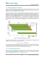
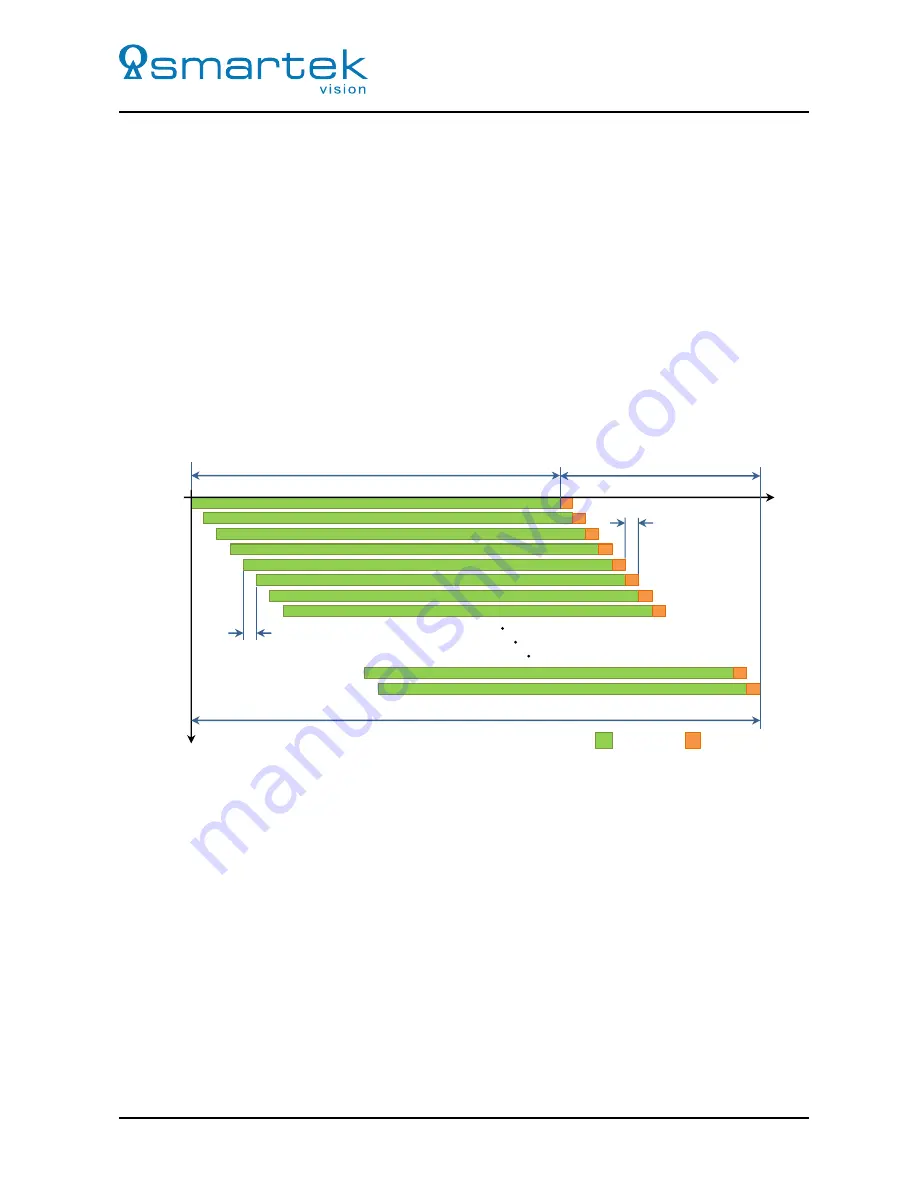
The process is shown in Figure 29; with the
Frame Start
signal, the exposure of line 1 is started. As
Electronic Rolling Shutter sensors are not able to store the load of pixels in a non-photon-sensitive area, the
exposure first ends with the individual pixel being read out. As the read out of all lines takes place in serial,
the read out of each line is delayed by the prior ones; to keep the duration of exposure for all lines equal, the
exposure start of each line is delayed about
t
ReadRow
to the prior line as well. Beside some internal timing
parameters and the read out frequency,
t
ReadRow
is mainly affected by the image width. The total time for
frame read out (
t
FrameReadout
) can be calculated by multiplying
t
ReadRow
with the total count of lines in the
frame.
t
ReadRow
t
ReadRow
t
FrameReadout
t
Frame
t
Exposure
t
Line 3
Line 4
Line 5
Line 6
Line 7
Line 8
Line N-1
Line N
Line 2
Line 1
.
.
.
Readout
Exposure
Frame
Start
Figure 29: Electronic Rolling Shutter Frame Readout
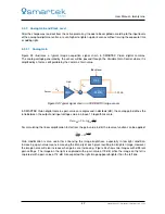
The duration of readout per frame can be calculated with the following formula, by multiplying the time
needed to read out each row with the total number of rows:
t
FrameReadout
=
t
ReadRow
×
ImageHeight
Due to the fact that the exposure duration of each line is shifted, each of them catches a different moment
of the scene, what leads to unwanted effects especially in moving scenes. This effects can be reduced or
completely removed in many cases by creating a controlled illumination situation.
4.3.2.1
Eliminating Rolling Shutter Effects
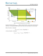
In many cases a strobe illumination or mechanical shutter can help to remove the rolling shutter
effect in moving scenes by putting light onto the sensor only while all lines are within integration. Figure 30
shows this illumination window as
t
Illumination
, staring at
t
IlluminationDelay
.
40
SMARTEK Vision | User Manual - twentynine | Doc. v1.0.2

