


HRM3300 REMOTE CONTROL MODULE USER MANUAL
HRM3300 Remote Control Module 2015-03-25 Version1.1 Page 10 of 9
buzzer and return flash indicator to its illuminating condition. In case of new
alarm situation, sound alarm will be initiated again and the light indicator will
start flashing and the user will have to press the acknowledge buttons again to
clear them.
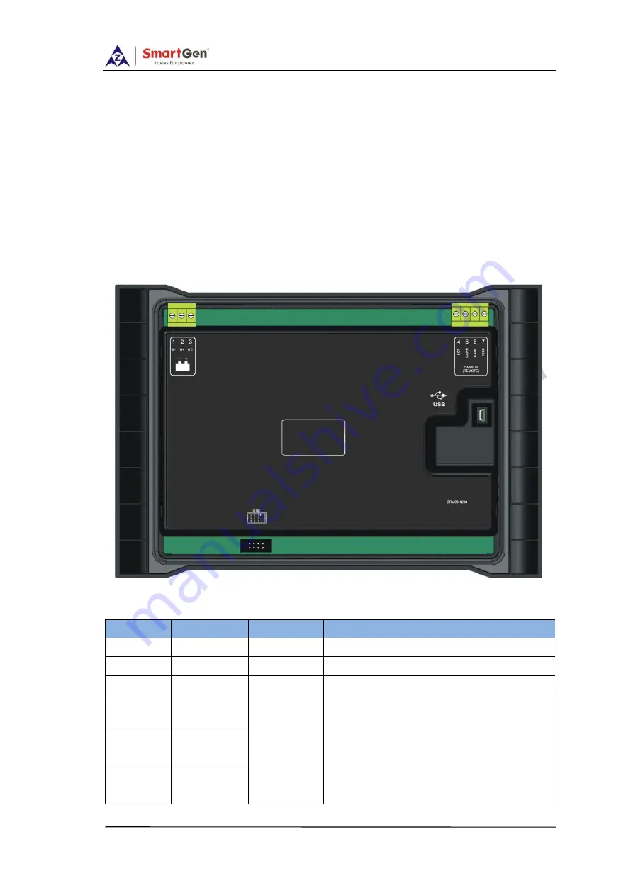
5. BACK PANEL
HRM3300
controller back panel is shown below
:
Terminal connections description
:
Terminal
Function
Cable Size
Description
1
B-
1.0mm
2
Power supply negative input.
2
B+
1.0mm
2
Power supply positive input.
3
NC
Not connected
4
SCR
(REMOTE)
0.5mm
2
A CANBUS port which communicate
with main control. Impedance-120
Ω
shielded wire with its one end
connected to ground is recommended.
There is 120Ω terminal resistance
inside already; if needed, make
5
CAN(H)
(REMOTE)
6
CAN(L)
(REMOTE)


