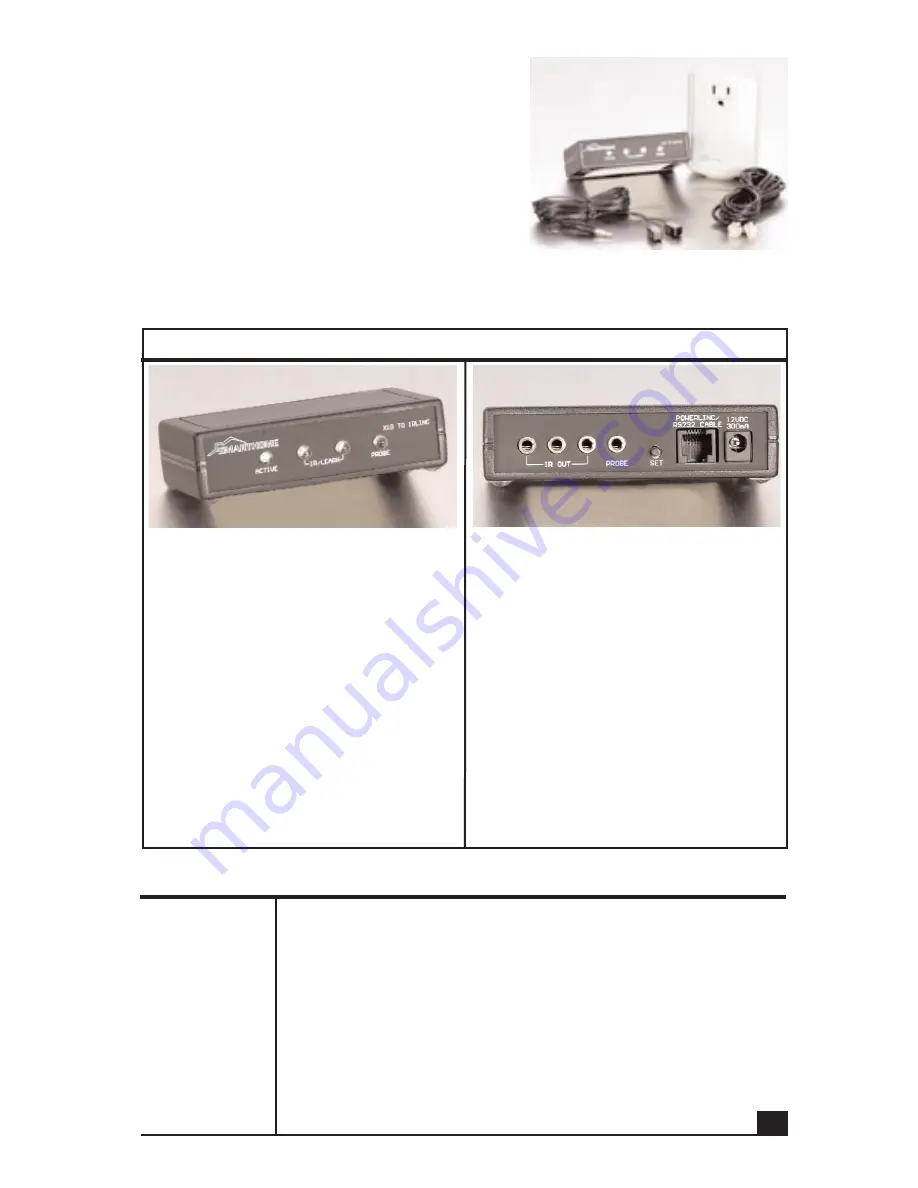
Parts included with the IR Linc kit
• The IR Linc controller box
• PowerLinc
TM
II PowerLine Adapter
• Double headed Stick-on IR Emitter
• PowerLinc II connecting cable
Please note that the PowerLinc II adapter is
designed to only work with the IR Linc controller
box. While it resembles our regular # 1132B
PowerLinc II adapter, the two are incompatible and not interchangeable. The includ-
ed PowerLinc adapter contains special circuitry and programming to support the IR
Linc control box.
Quick Start Instructions
Learning
an IR
Command
1. Press and hold the "Set" button for about one second.
The red "Active" indicator will begin to blink rapidly.
2. Press the button on the teaching remote.
Once the "Active" indicator turns off, release the button on
the remote control.
3. The green "Probe" indicator will begin to flash indicating
that the IR Linc is ready to receive PLC commands to asso-
ciate with the learned IR signal.
4. Send the PLC signal.
The green indicator will turn on solid, then off.
(See page 6 for more detailed instructions)
Overview
• The
Active
indicator will show that
the unit is ready to learn IR signals.
During normal use, it will blink when
IR signals are transmitted.·
• The two
IR/Learn
blast emitters
emit IR light to control the AV
devices. During programming, they
sense the IR light from the teaching
remote.·
• The
Probe
indicator is used to indi-
cate when a Smarthome probe is
detecting an ON condition. It is also
used to during learning and will blink
when PLC/X10 signals are detected
on the power line.
• The three
IR Out
jacks for optional
external IR emitters.
• The
Probe
jack will accept the
Smarthome Probes to monitor the
power status of equipment.
• The
Set
button is will put the IR Linc
into the learning mode, clear learned
commands, or clear the memory.
• The
Powerlinc/RS232 Cable
jack
connects to PowerLinc II supplied
with the IR Linc.
• The
12VDC, 300mA
is not used on
the IR Linc, power for the unit is sup-
plied by the PowerLinc II adapter.
3


