background image

DE5457P

13

6.3 Phone Line Test Interval

Here you determine the time interval between consecu-
tive tests of the telephone line. The control panel does it
at regular intervals to verify that the line is operational.
However, be advised that the first test will take place 12
hours after you exit the installer mode.
The options are: 

test every 1

5

7

,

 30 days

 and 

test off

.

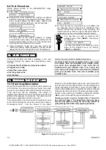
Upon selecting Location 02, the display will change to:


0 2 : L I N E   T E S T

Select the desired option as outlined in Para. 6.1 C above.

6.4 First Central Station Telephone     

Here you program the telephone number of the first
central station to which the 

SECURELINC

 will report the

event groups defined in memory location 09.

Upon selecting Location 03, the display will change to:


0 3 : 1 S T


C N T R   T E L


Enter the first central station’s telephone number (16 digits
max.) as outlined in Para. 6.1 D above.

6.5 First Account No.

Here you enter the account number that will identify your
specific alarm control system to the 1

st

 central station.

The number consists of 4 hexadecimal digits.

Upon selecting Location 04, the display will change to:


0 4 : 1 S T   A C C O U N T   #

Enter the account no. as outlined in Para. 6.1 D above.

6.6 Second Central Station Telephone

Here you program the telephone number of the second
central station to which the 

SECURELINC

 will report the

event groups defined in memory location 09.

Upon selecting Location 05, the display will change to:


0 5 : 2 N D


C N T R   T E L


Enter the second central station’s telephone number as
outlined in Para. 6.1 D above.

6.7 Second Account No.

Here you enter the account number that will identify your
particular alarm control system to the 2

nd

 central station.

The account number consists of 4 hexadecimal digits.

Upon selecting Location 06, the display will change to:


0 6 : 2 N D   A C C O U N T   #

Enter the account no. as outlined in Para. 6.1 D above.

6.8 Report Format

Here you select the reporting format used by the control
panel to report events to central stations.
The options are: 

&


Contact-ID  

&


SIA 

&

 4/2 1900/1400

&

 4/2 1800/2300  

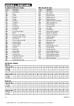
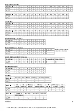
(for code lists - see Appendix A).

Upon selecting Location 07, the display will change to:


0 7 : R E P O R T   F O R M A T

Select the desired option as outlined in Para. 6.1 C above.

6.9 4/2 Pulse rate

Here you select the pulse rate at which data will be sent
to central stations if any one of the 4/2 formats has been
selected in Location 07.

The options are: 

10

20

33

 and 

40

 pps

Upon selecting Location 08, the display will change to:


0 8 : 4 / 2   P L S   R A T E

Select the desired option as outlined in Para. 6.1 C above.

6.10 Events Reported to Central

Stations

Here you determine which types of event will be reported
to central stations. Due to lack of space in the display,
abbreviations are used: alarm is “

alrm

”, alert is “

alrt

” and

open/close is “

o/c

”. The asterisk (

)


is a separator

between events reported to 

central station 1

 and events

reported to 

central station 2

.

Messages are divided by type into three groups:

GROUP EVENTS 

REPORTED

Alarms

Fire, Burglary, Panic, Tamper

Open/Close

Arming AWAY, Arming HOME, Disarming

Alerts

No-activity, Emergency, Latchkey

Group 1 has the highest priority and group 3 has the

lowest  priority.
The selectable options are shown in the following table:

Plan name

Sent to center 1

Sent to center 2

all 

 backup

All events

all –o/c 

 backup

All but open/close

all 

 all

All events

All events

all –o/c 

 all –o/c

All but open/close

All but open/close

all –o/c 

 o/c

All but open/close

open/close only

all (–alrt) 

 alrt

All but alerts

Alerts

alrm 

 all (–alrm)

Alarms

All but alarms

disable

Nothing

Nothing

Note:

  “

All

” means that all 3 groups are reported and also

trouble messages - sensor / system low battery, sensor

inactivity, power failure, jamming and communication failure.

Upon selecting Location 09, the display will change to:


0 9 : R E P O R T

C N T R

Select the desired option as outlined in Para. 6.1 C above.  

6.11 Dialing Attempts

Here you determine how many times the communicator
will dial the central station’s number.
The options are: 

2

4

8

12

, and

 16 

attempts.

Attention!

 A maximum of 2 dialing attempts is permitted

by the Australian Telecommunication Authority.

Upon selecting Location 10, the display will change to:


1 0 : D I A L   A T T E M P T S

Select the desired option as outlined in Para. 6.1 C above.

6.12 First Private Telephone No.

Here you program the telephone number of the first

private subscriber to which the system will report the

event groups defined in Location 16.

Upon selecting Location 11, the display will change to:


1 1 : 1 S T   P R V T   T E L #

Enter the first private subscriber’s telephone number as

outlined in Para. 6.1 D above.

All if center 1
does not respond

}

SMARTHOME.COM™  1-800-SMART-HOME  949-221-9200  http://www.smarthome.com  Order #73902

Summary of Contents for Securelinc

Page 1: ...st Central Station Telephone 13 6 5 First Account No 13 6 6 Second Central Station Telephone 13 6 7 Second Account No 13 6 8 Report Format 13 6 9 4 2 Pulse Rate 13 6 10 Events Reported to Central Stations 13 6 11 Dialing Attempts 13 6 12 First Private Telephone No 13 6 13 Second Private Telephone No 14 6 14 Third Private Telephone No 14 6 15 Telephone Message Type 14 6 16 Private Tel Dialing Attem...

Page 2: ...successful completion of an operation Sad Melody indicates a wrong move or rejection 1 2 Accessing the Installer s Menu To access the installer s menu and navigate within it refer to Figures 1 and 2 and proceed as follows A Click the NEXT button until the display reads I N S T A L L E R M O D E B Click OK to select the installer s mode The control panel will prompt you for the installer code C Ent...

Page 3: ... N R O L L I N G C Click OK to select the enroll wireless devices sub mode The display will change to E N R O L L W L D E V I C E D Click OK again The display will read Z o n e N o _ _ E Suppose that the wireless device you are about to enroll is to be installed in Zone No 4 Assuming that zone No 4 is free no device has yet been enrolled to it just enter 0 4 The display will change to Z o n e N o ...

Page 4: ...continue in several different directions If you wish to enroll another keyfob select the desired number by Clicking NEXT to go up 6 7 8 Clicking BACK to go down 4 3 2 Clicking HOME desired zone After that proceed as in the example above To delete keyfob IDs refer to Para 3 4 To return to the main menu click AWAY This will bring back the display O K T O E X I T You may now review and select any oth...

Page 5: ...ONE NAME LIST Attic Back door Basement Bathroom Bedroom Child room Closet Den Dining room Downstairs Emergency Fire Front door Garage Garage Door Guest room Hall Kitchen Laundry room Living room Master bath Master Bdrm Office Upstairs Utility room Yard Custom 1 Custom 2 Custom 3 Figure 3 DEFINE ZONES Flow Chart 4 2 Zone Definition Procedure Once 3 DEFINE ZONES is viewed proceed as follows A Click ...

Page 6: ...nd the display will revert to Z o n e N o 0 7 L From this point on you may continue in several different directions Click NEXT to go up 8 9 10 Click BACK to go down 6 5 4 Repeat Steps C through K above for all other zones that you plan to use To return to the main menu click AWAY This will get you back to O K T O E X I T You may now review and select any other mode on the installer s menu by click...

Page 7: ... and adapt its characteristics and behavior to the requirements of the particular user Should you wish to get an overall view of the entire programming process refer to the programming chart in Figure 4 You may even use the chart as your only guide along the programming process instead of going through the written step by step procedure Figure 4 DEFINE PANEL Flow Chart SMARTHOME COM 1 800 SMART HO...

Page 8: ...en done Click NEXT to select Location 3 5 3 Exit Delay An exit delay allows the user to arm the system and leave the protected site via specific routes and doors without causing an alarm Slow rate warning beeps will start sounding once the arming command has been given This will continue until the last 10 seconds of the delay throughout which the beeping rate will increase Location No 3 allows you...

Page 9: ...ermine how many times each zone is allowed to initiate an alarm within a single arming period If the number of alarms from a specific zone exceeds the number programmed in this location the control panel will automatically bypass the zone to prevent recurrent siren noise and nuisance reporting to the central station The zone will remain bypassed until disarming The available options are shut after...

Page 10: ...ming Here you determine whether the system can be armed in the latchkey mode If the system is armed this way a latchkey message will be sent to specific telephones upon disarming by a latchkey user users 5 through 8 or keyfob transmitters 5 through 8 This mode is useful when parents at work want to be informed of a child s return from school The options are Latchkey ON and Latchkey OFF Upon select...

Page 11: ...ox at the far right S I A If you approve of this option click OK The Happy Tune will sound and the number and name of the present memory location will be re displayed If you do not approve review the other options by clicking NEXT or BACK repeatedly Options that are not saved will have a clear space at the far right as shown c o n t a c t I D To select an option that is not the currently saved one...

Page 12: ... by the automatic dialer built into the SECURELINC control panel The options are Pulse and DTMF Upon selecting Location 01 the display will read 0 1 D I A L M E T H O D Select the desired option as outlined in Para 6 1 C above SMARTHOME COM 1 800 SMART HOME 949 221 9200 http www smarthome com Order 73902 ...

Page 13: ...ct the pulse rate at which data will be sent to central stations if any one of the 4 2 formats has been selected in Location 07 The options are 10 20 33 and 40 pps Upon selecting Location 08 the display will change to 0 8 4 2 P L S R A T E Select the desired option as outlined in Para 6 1 C above 6 10 Events Reported to Central Stations Here you determine which types of event will be reported to c...

Page 14: ...vent closed and call off the communication session The remaining telephones serve for backup purposes only In the all acknowledge mode an acknowledge signal must be received from each telephone before the current event is considered reported The options are single ack and all ack Upon selecting Location 17 the display will change to 1 7 T E L E P H O N E A C K Select the desired option as outlined...

Page 15: ...y Guidance A Mode description This mode allows you to select events and conditions under which the PGM programmable output and X 10 outputs will function There are two kinds of memory locations in this sub mode each of which requires a different programming method Multiple Choice Locations these memory locations allow you to choose one of several options see C below for programming method Numerica...

Page 16: ...E P G M B Click OK The display will change into O N B Y A R M I N G C Select the desired option YES or NO as outlined in Para 7 1 C above When done click NEXT to select the next item on the menu D Go through the next 3 menu items ON BY MEMORY ON BY DELAY and ON BY KEFOB selecting the desired option for each After that clicking NEXT will change the display into O N B Y T I M E R E Click OK The disp...

Page 17: ...EW INSTL CODE B Click NEXT until the 7th mode is displayed 7 R E C O R D S P E E C H 8 2 Recording Procedure Having gained access to the RECORD SPEECH mode you can now record the house identity A Click OK The display will change into H O U S E I D E N T I T Y B Press the 2 key until this is displayed briefly R E C O R D A M E S S A G E Immediately thereafter the display will change into T A L K N ...

Page 18: ...s Select the voice option Set the system clock Set the Date Refer to the User Guide for detailed procedures Caution If after having programmed the user codes the system does not recognize your installer code you must have programmed a user code that is identical with your installer code If so access the user menu and change the code which is identical with your installer code This will re validate...

Page 19: ...e event log times out 4 minutes D Click OK as many times as necessary to read all the data you need To clear the event log refer to Para 11 3 To quit the event log Click HOME or AWAY from any where within the log The display will read O K T O E X I T Click OK The system will return to the normal operating mode 11 3 Erasing the Event Log A From anywhere within the event log click NEXT The display w...

Page 20: ... Report FA Fire Alarm FR Fire Restore HA Holdup Alarm duress LR Phone Line Restore LT Phone Line Trouble OP Opening Report PA Panic Alarm QA Emergency Alarm RP Automatic Test RX Manual Test RY Exit from Manual Test TA Tamper Alarm TR Tamper Restore XR Sensor Battery Restore XT Sensor Battery Trouble YR System Battery Restore YT System Battery Trouble YX Service Required 4 2 Event Codes Alarms Zone...

Page 21: ...igit 1 2 3 4 5 6 7 8 Panic 24 Hours 8 users User No 1 2 3 4 5 6 7 8 Panic CP Note Panic and Duress 1st digit 2 2 2 2 2 2 2 2 2 share the same code 2nd digit 1 2 3 4 5 6 7 8 9 Arm HOME and AWAY Closing User No 1 2 3 4 5 6 7 8 Cancel alarm Recent Close 1st digit E E E E E E E E E E 2nd digit 1 2 3 4 5 6 7 8 9 C Disarm Opening User No 1 2 3 4 5 6 7 8 1st digit F F F F F F F F 2nd digit 1 2 3 4 5 6 7 ...

Reviews: