DE5457P
15
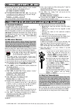
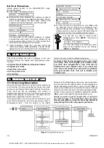
Upon selecting Location 22, the display will change to:
2 2 : R E M O T E A C C E S S
Select the desired option as outlined in Para. 6.1 C above.
6.24 Downloader Code
Here you determine the 4-digit code used as a password
for downloading data into the
SECURELINC
memory.
Upon selecting Location 23, the display will change to:
2 3 : D O W N L O A D C O D E
Enter the 4-digit code as outlined in Para. 6.1 D above.
Attention! Do not use “0000” - this code is invalid.
Having thus completed a full cycle of all 23 communication
parameters, you may now continue by defining output
parameters (see Section 7).
If at this point you wish to return to the
installer’s menu, click <
AWAY
>. This will get
you back to:
< O K > T O E X I T
You may now review and select any other
mode on the installer’s menu (by clicking
<
NEXT
> or <
BACK
>).
7
77
7. DEFINING OUTPUT PARAMETERS
. DEFINING OUTPUT PARAMETERS
. DEFINING OUTPUT PARAMETERS
. DEFINING OUTPUT PARAMETERS
7.1 Preliminary Guidance
A. Mode description
This mode allows you to select events and conditions
under which the PGM (programmable) output and X-10
outputs will function.
There are two kinds of memory locations in this sub-mode,
each of which requires a different programming method:
&
Multiple Choice Locations:
these memory locations
allow you to choose one of several options (see C
below for programming method)
&
&
&
&
Numerical Data Locations:
these memory locations
accept digital data (a code, a time limit etc. - see D
below for programming method).
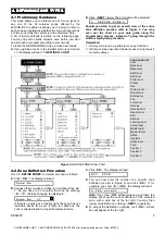
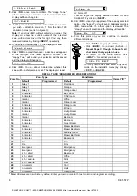
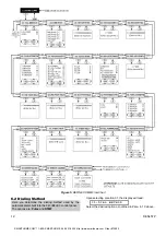
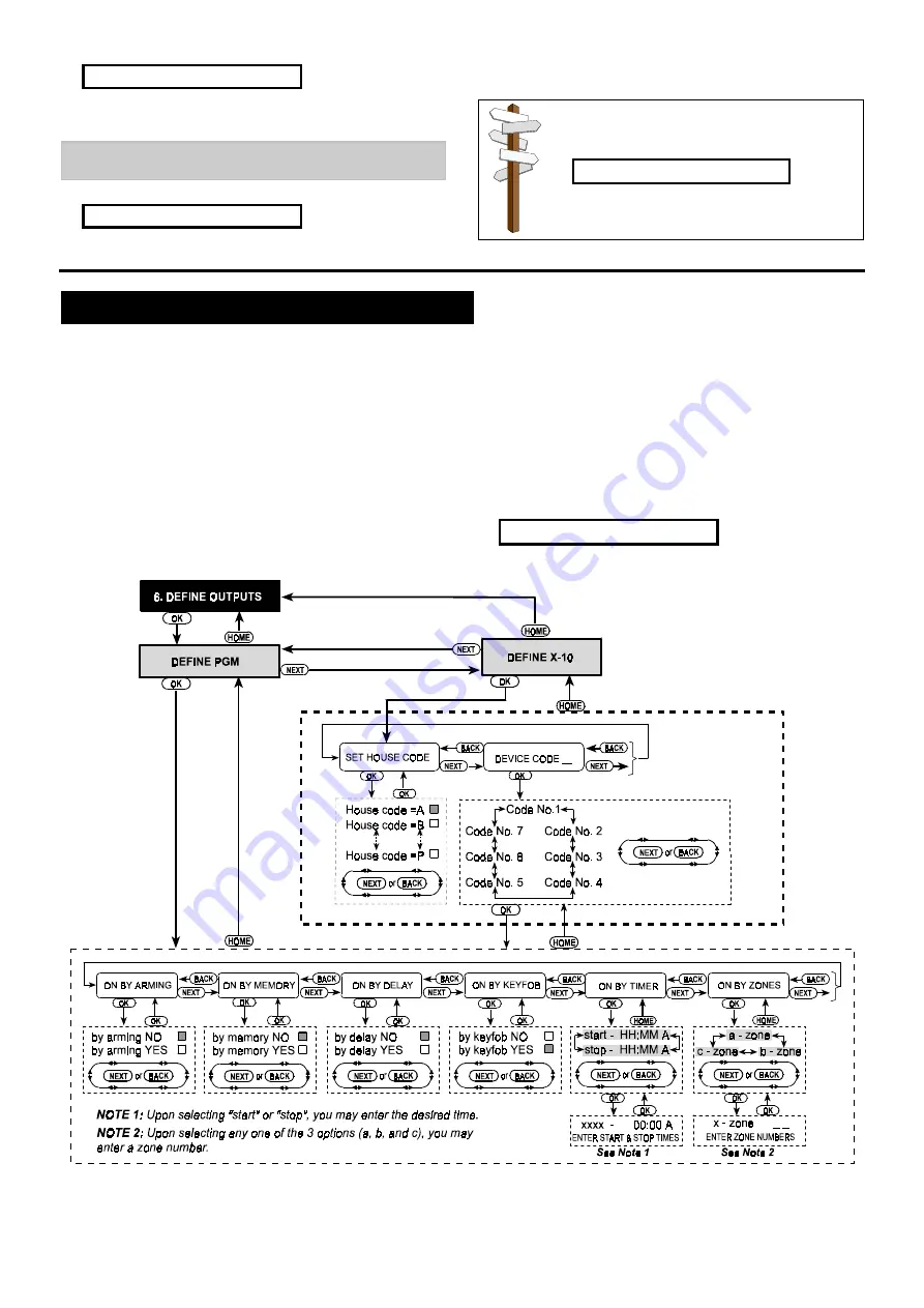
Should you wish to get an overall view of the entire
process, refer to the programming chart in Figure 6.
You may even use the chart as your only guide along
the programming process, instead of going through
the written step-by-step procedure.
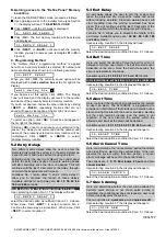
B. Gaining Access to the “Define Outputs” Mode
&
&
&
&
Upon gaining access to the installer menu (see Section
1), the display will read “
1. NEW INSTL CODE
”.
&
&
&
&
Click <
NEXT
> until the 6th mode is displayed:
6 . D E F I N E O U T P U T S
&
&
&
&
Click <
OK
>. The display will show the first sub-mode:
Figure 6.
DEFINE OUTPUTS Flow Chart
SMARTHOME.COM™ 1-800-SMART-HOME 949-221-9200 http://www.smarthome.com Order #73902


