DE5457P
9
5.8 Forced Arming
Here you determine whether the user will be allowed to
perform forced arming or not. If forced arming is
permitted, the control panel will automatically bypass
zones that were open throughout the exit delay (but not
delay zones). If forced arming is not permitted, “NOT
READY” will be displayed and arming will be refused (the
“Sad Melody” will sound).
The two options are:
force arm
ON
and
force arm
OFF
.
In UL installations, OFF must be selected (no forced
arming).
Upon selecting Location 08, the display will change to:
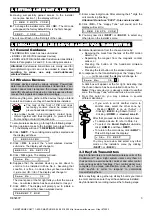
0 8 : F O R C E A R M
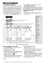
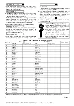
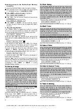
Select the desired option as outlined in Para. 5.1 C above.
5.9 Restart Exit
Here you determine whether the exit delay will restart if
the exit / entry door is reopened before the exit delay
expires. Restarting the exit delay is helpful if the user
re-enters immediately after going out to retrieve an item
that he left behind.
The two options are:
restart ON
and
restart OFF
.
Upon selecting Location 09, the display will change to:
0 9 : R E S T A R T E X I T
Select the desired option as outlined in Para. 5.1 C above.
5.10 Piezo Beeps
Here you determine whether warning beeps will sound or
will be muted throughout the exit and entry delays. An
additional option is to mute the warning beeps only when
the system is armed “HOME”.
Three options are available:
enable beeps
,
off when
home
and
disable beeps
.
Upon selecting Location 10, the display will change to:
1 0 : P I E Z O B E E P S
Select the desired option as outlined in Para. 5.1 C above.
5.11 Trouble Beeps
Under trouble conditions, the sounder emits a series of 3
short beeps once per minute. Here you determine
whether this special beeping sequence will be active,
inactive, or just inactive at night (the range of “night”
hours is defined in the factory).
The 3 options are:
enable beeps
,
off at night (8 PM
through 7 AM)
and
disable beeps
.
Upon selecting Location 11, the display will change to:
1 1 : T R O U B L E B E E P S
Select the desired option as outlined in Para. 5.1 C above.
5.12 Panic Alarm
Here you determine whether the user will be allowed to
initiate a panic alarm by simultaneous pressing of the two
panic buttons (on the keypad) or away + home (on a
keyfob transmitter).
The two options are:
enable panic
and
disable panic
.
Upon selecting Location 12, the display will change to:
1 2 : P A N I C A L A R M
Select the desired option as outlined in Para. 5.1 C above.
5.13 Swinger Stop
Here you determine how many times each zone is
allowed to initiate an alarm within a single arming period.
If the number of alarms from a specific zone exceeds the
number programmed in this location, the control panel
will automatically bypass the zone to prevent recurrent
siren noise and nuisance reporting to the central station.
The zone will remain bypassed until disarming.
The available options are:
shut after 1
,
shut after 2
,
shut after 3
and
no shutdown
.
In UL installations, No Shutdown must be selected.
Upon selecting Location 13, the display will change to:
1 3 : S W I N G E R S T O P
Select the desired option as outlined in Para. 5.1 C above.
5.14 Cross Zoning
Here you determine whether cross zoning will be active
or inactive. Cross zoning is a method used to counteract
false alarms - an alarm will not be initiated unless two
adjacent zones are violated within a 30-second time limit.
This feature is active only when arming AWAY and only
with zone couples from zone No. 20 up (20 and 21, 22
and 23, etc.). You may use any one of these zone
couples to create a “cross-zoned” area.
The options are:
cross zone ON
and
cross zone OFF
.
Upon selecting Location 14, the display will change to:
1 4 : C R O S S Z O N I N G
Select the desired option as outlined in Para. 5.1 C above.
5.15 Supervision Interval
Here you determine the time limit for reception of
supervision reports from supervised wireless devices. If
any device does not report at least once within the
selected time limit, an “INACTIVITY” alert will be initiated.
The options are:
1
,
2
,
4, 8, 12 hours
and
disable.
In UL installations, the interval must not exceed 4 h.
Upon selecting Location 15, the display will change to:
1 5 : S U P E R V I S I O N
Select the desired option as outlined in Para. 5.1 C above.
5.16 AUX Button
Here you select the function of the AUX button on keyfob
transmitters. Three options are offered:
Status:
Pressing the AUX button will cause the control
panel’s voice module to announce the system status.
Instant:
Pressing the AUX button while the exit delay is
in progress will cause the system to arm “instant” (the
entry delay is cancelled).
PGM / X-10:
Pressing the AUX button will activate the
PGM output or X-10 units (see further programming
under “DEFINE OUTPUTS”).
Upon selecting Location 16, the display will change to:
1 6 : A U X B U T T O N
Select the desired option as outlined in Para. 5.1 C above.
5.17 Jamming Detection
Here you determine whether jamming (interfering
transmissions) on the radio channel used by the system
will be detected and reported or not.
SMARTHOME.COM™ 1-800-SMART-HOME 949-221-9200 http://www.smarthome.com Order #73902


