OM_Axessor_CIT_V024_20170518_EN.pdf Operating
Manual
Page 28
Subject to change without prior notice
Axessor CIT
4.6
External connections at the lock
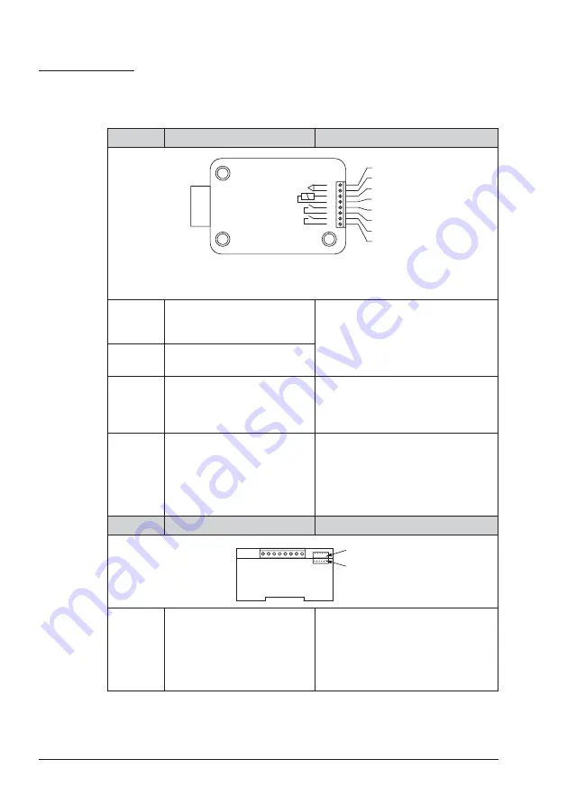
If desired, connect additional external signals at the lock terminal block.
Refer to the table and the wiring examples below.
Terminal
Description
Capacity / Remarks
12345678
IN2
GND
IN1+
IN1-
OUT1 A
OUT1 B
OUT2 A
OUT2 B
Note: Function and polarity of the Inputs and Outputs can be
changed with optional AS284-USBW or AS284-NETW Programming Soft-
ware.
1 / 2
Output 2
standard: bolt or motor
open
30 VDC/2A, 50 VAC/0.5A
with resistive load.
Relay with potential-free working
contacts (NO - normally open).
3 / 4
Output 1
standard: Duress alarm
5(–) /
6(+)
Input 1
standard: not assigned
optional: remote disabling,
or controlled disabling
12 VDC (min. 20mA)
7 / 8
Input 2
standard: not assigned
optional: Programmable
with AS284-USBW or
AS284-NETW Programming
Software
Do not apply any voltage – poten-
tial free contact only!
Recommendation: Suitable micro
switch with gold-plated contacts
for 12 VDC/50mA (e.g. „DB series“
by Cherry).
Socket
Description
Capacity / Remarks
1 2 3 4 5 6 7 8
X1
X2
X1, X2
Connection to input unit or
to eBox
or
Connection of power supply
Enclosed connection cable must
be used.
Use only the original Axessor
power supply that is available as
optional accessory
Summary of Contents for Axessor CIT
Page 1: ......


