background image

ASSEMBLY INSTRUCTIONS – POND KIT 


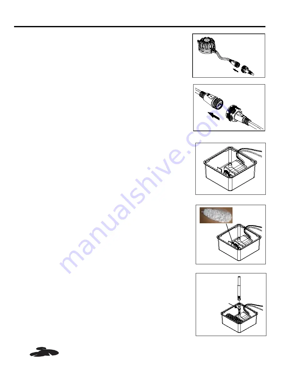
1.  Connect the light  to the sensor by pushing the plug into the 

sensor socket until it is firmly seated. Hand tighten the nut from 
the plug to the socket.  Fig. 5 


Fig. 5 

2.  Connect the sensor  to the pump by pushing the plug into the 

socket until it is firmly seated. Hand tighten the nut from the plug to 
the socket.  Fig. 6 


 Fig. 6 

3.  Place the pump assembly inside the filter box base. Make sure that 

the outlet points up.  Route the cord through the gap on side of the 
filter box base.  Fig. 7 


                                                                                                                                                 Fig. 7 

4.  Place the bio ball inside the filter box base in front of pump. Fig. 8 


                                                                                                                                                 Fig. 8 

5.  Connect the extension tube to the outlet of the pump using the 

supplied adapter. Fig 9 


Fig. 9 


Plug from 

sensor 

Socket from 

pump 


Extension tube 

Adapter 


Sensor 

Plug from 

lights 

PLEASE CALL 1-888-755-4497 BEFORE RETURNING TO THE STORE. 

                      WWW.SMART-POND.COM 

Summary of Contents for CPK500

Page 1: ...nozzle insert 1 L Lower fountain head nozzle 1 M Adapter with o ring 1 N Liner 7 ft X 10ft 1 P Liner patch 1 A M L K J I H B E F P N D C G Questions problems missing parts Before returning to your retailer call our customer service department at 1 888 755 4497 8 a m 6 p m EST Monday Friday or email us at customercare smart pond com REMINDER CALL 1 888 755 4497 BEFORE RETURNING TO STORE PLEASE CALL...

Page 2: ...emperatures or other heat sources Do not pump heated liquids Do not let the pump run dry Pump must be completely submerged for proper operation and cooling Operate in freshwater only Avoid heavily chlorinated water and water with high pH levels Do not lift the pump by its power cord PREPARATION LINER Before installing your pond liner make sure it is in good condition with no tears or holes If you ...

Page 3: ... 2 3 Open the liner and drape it across the pond area making sure to leave at least 10 in of overlap around the perimeter of the hole Begin to fill the pond with water smoothing out any wrinkles as you do this Fig 3 Fig 3 4 When the pond is full bury the excess liner in a small trench around your pond with stones and rocks according to your landscape design Fig 4 Fig 4 PLEASE CALL 1 888 755 4497 B...

Page 4: ...plug to the socket Fig 6 Fig 6 3 Place the pump assembly inside the filter box base Make sure that the outlet points up Route the cord through the gap on side of the filter box base Fig 7 Fig 7 4 Place the bio ball inside the filter box base in front of pump Fig 8 Fig 8 5 Connect the extension tube to the outlet of the pump using the supplied adapter Fig 9 Fig 9 Plug from sensor Socket from pump E...

Page 5: ...Make sure that the sensor is NOT submerged Make sure that the light sensor faces up Fig 12 NOTE At night the lights will automatically turn on At sunrise they will automatically turn off Fig 12 9 Place the filter assembly into the pond and connect to a proper power source Fig 13 Fig 13 GFCI Filter box cover Filter pad I H H H L K L J Sensor Must face up PLEASE CALL 1 888 755 4497 BEFORE RETURNING ...

Page 6: ...mble the front cover and remove the impeller cover to expose the impeller assembly Remove the impeller assembly by gently pulling on the impeller blades Use a soft cloth or brush to clean the impeller assembly and the inside of the impeller housing CARE AND MAINTENANCE LIGHT Periodically your lights may require cleaning for optimal performance Cleaning should only be done with warm soapy water Be ...

Page 7: ...Waterspray nozzle J Waterbell nozzle insert K Trumpet nozzle insert L Lower fountain head nozzle M Adapter with o ring Q Flow control knob R Front cover S Locking ring T Impeller cover U Shaft support V Washer W Shaft X Impeller assembly Y Lamp retaining ring Z Lens A1 O ring A2 Reflector A3 Locking nut A4 Adjust ball pin A5 Base A M L K J I H B E F U T S R W X V U Q C Y Z A1 A2 A3 A4 A5 G V PLEAS...

Page 8: ...y does not cover any costs associated with the shipping handling installation or removal of products or parts subject to this warranty For products damaged in transit a claim should be filed with the carrier Disclaimer Any oral statements made about the product by the seller the manufacturer the representatives or any other parties do not constitute warranties should not be relied upon by the user...

Reviews: