background image

2

!

DURING THIS TEST THE BULB WILL QUICKLY BECOME HOT TO THE TOUCH. ONCE THE LIGHT
HAS SUCCESSFULLY PASSED THIS TEST, BE SURE TO TURN THE LIGHT OFF AS PROLONGED
USE OUT THE WATER MAY DAMAGE THE UNIT AND VOID THE WARRANTY.

TESTING LIGHT FUNCTION

• Plug the light into a GFI protected outlet and turn the switch to the ON position (red light will illuminate). 

o If the light does not illuminate, turn the switch OFF, check the bulb for a secure fit, and try to run the light again.

o If the light still does not turn on, contact SmartPool Technical Support at (732) 730-9880.

FIGURE 3

INSTALLING THE BULB

• Place the light on a table or a flat, dry surface.

• Insert the latch key into the locking latch, turn the key to the left and hold in position as shown 

in Figure 1. 

• Rotate the Seal Ring counter clockwise to loosen as shown in Figure 2.  

• Remove the Seal Ring and lens.

• Remove the bulb from its box, being careful not to touch the face of the bulb.

• Insert the legs of the bulb into the ceramic outlet shown in Figure 3.

DO NOT PLUG LIGHT IN UNTIL INSTRUCTED IN MANUAL

Locking Latch

FIGURE 1

FIGURE 2

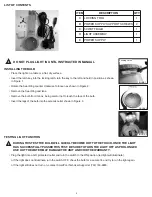
ITEM

DESCRIPTION

QTY

A

LOCKING TOOL

1

B

POWER SUPPLY SUPPORT SCREWS

2

C

50 WATT BULB

1

D

LIGHT ASSEMBLY

1

E

POWER SUPPLY

1

LIST OF CONTENTS

!

A

B

C

D

E

Summary of Contents for NiteLighter NL50

Page 1: ...ot connect unit to AC power until installation has been completed WARNING Do not use if unit is damaged in any way WARNING Unit must be submerged below the minimum water level or warranty is void WARNING DO NOT USE EXTENSION CORDS DEATH OR INJURY CAN RESULT WARNING Make sure the light is unplugged from its power supply before opening the unit or performing any other maintenance WARNING To protect ...

Page 2: ...t SmartPool Technical Support at 732 730 9880 FIGURE 3 INSTALLING THE BULB Place the light on a table or a flat dry surface Insert the latch key into the locking latch turn the key to the left and hold in position as shown in Figure 1 Rotate the Seal Ring counter clockwise to loosen as shown in Figure 2 Remove the Seal Ring and lens Remove the bulb from its box being careful not to touch the face ...

Page 3: ...e 5 screws may have to be removed Slide the light onto the pool wall so that the light is centered in the middle of the top ledge Hold the light so the mounting bracket is flush with the top of the pool wall and turn the Thumb Wheel in a clockwise direction to secure the light to the wall as shown in Figure 6 Be sure the wire runs through the Wire Channel of the Mounting Bracket Reinstall the top ...

Page 4: ...R CHARGES FOR LABOR SMARTPOOL SHALL NOT BE LIABLE OR RESPONSIBLE UNDER ANY CIRCUMSTANCES OR ANY AMOUNT FOR ANY CONSEQUENTIAL OR INCIDENTAL DAMAGES OR FOR ANY INJURIES OR DAMAGES TO PERSON OR PROPERTY USING OR USED IN CONNECTION WITH THE PRODUCT OR FOR ANY OTHER LOSS OF PROFITS OR OTHER COSTS OR EXPENSES OF ANY KIND OR CHARACTER IF SMARTPOOL LLC DETERMINES THAT EITHER REPAIR OR REPLACEMENT OF THE P...

Reviews: