background image

3

3.System Description

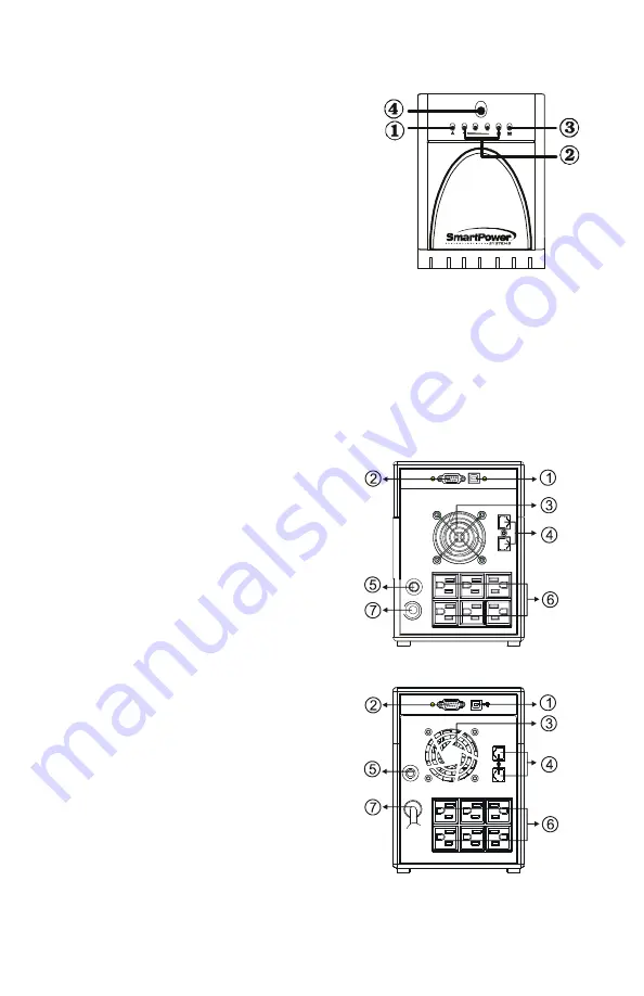
Front Panel—LED

1.  Fault LED 

2.  AC Mode: Load Level LEDs 

Backup Mode: Battery Capacity LEDs 

3.  AC Mode: Green Lighting 

Backup Mode: Green Flashing 

4.  Power “ON/OFF” Switch 


+ -


Back Panel


1.  USB Port (Option) 

2.  RS232 Por t 

3.  Cooling Fan 

4.  Modem/Phone Line Surge Protection 

5.  Circuit Breaker 

6.  AC Output 

7.  AC Input 


SBP1400TBF/SBP2000TBF

SBP1000TBF

Summary of Contents for SBP1000TBF

Page 1: ...USER S GUIDE Uninterruptible Power Supply 1000VA 1400VA 2000VA Models SBP1000TBF SBP1400TBF SBP2000TBF SBP TBF UPS Series P N 16002100 Rev 03 16 11 SmartPower SYSTEMS A POWER QUALITY COMPANY ...

Page 2: ...beverages or any other liquid containing vessels on or near the unit This unit intended for installation in a controlled environment temperature controlled indoor area free of conductive contaminants Avoid installing the UPS in locations where there is standing or running water or excessive humidity Do not plug the UPS input into its own output Do not attach a power strip or surge suppressor to th...

Page 3: ...should be observed when working on batteries 1 Remove watches rings or other metal objects from the hand 2 Use tools with insulated handles 3 Wear rubber gloves and boots 4 Do not lay tools or metal parts on the top of batteries 5 Disconnect charging source prior to connecting or disconnecting batteries terminal Servicing of batteries should be performed or supervised by personnel knowledgeable of...

Page 4: ...s Backup Mode Battery Capacity LEDs 3 AC Mode Green Lighting Backup Mode Green Flashing 4 Power ON OFF Switch Back Panel 1 USB Port Option 2 RS232 Por t 3 Cooling Fan 4 Modem Phone Line Surge Protection 5 Circuit Breaker 6 AC Output 7 AC Input SBP1400TBF SBP2000TBF SBP1000TBF ...

Page 5: ...d the unit and is free from excessive dust corrosive fumes and conductive contaminants Do not operate your UPS in an environment where the ambient temperature or humidity is high On the other hand place the UPS unit away from monitor at least 8 inches to avoid interference 3 Charging This unit is shipped from the factory with its internal battery fully charged however some charge may be lost durin...

Page 6: ...mum of three devices 5 Modem Phone line Connection Plug incoming internet line into the In socket at the back of the UPS Use one more Internet line cable and plug one end of the Internet line cable to the Out socket at the back of the UPS Plug the other end to the modem input socket as shown 5 COMPUTER UPS Incoming Internet line ...

Page 7: ... press power switch again Please DO NOT punch it to extend the life of the power switch 8 DC Start Function DC Start Function enables UPS to be started up when AC utility power is not available and battery is fully charged Just simply press the power switch to turn on the UPS 9 Green Power Function All UPS are equipped with Green Power function If no load connects to the UPS it will automatically ...

Page 8: ...nnected to the battery Be sure to replace the same type of batteries and dispose of old batteries properly at an appropriate recycling facility Before replacing the battery turn off the UPS and unplug the UPS cord from the wall outlet Follow Chart 4 to remove the screw located on the bottom of the front panel and then open the front cover Remove the front panel Remove the battery cover ...

Page 9: ...wer condition analysis Online display of input output voltage and frequency battery capacity and load level Dashboard interface Send on line commands to UPS such as Test Shutdown Sleep and restart Extensive logging of all UPS operation and power quality data Event date analysis Events and data bar charts presentation Graphical display of power quality Run in background even before user login Free ...

Page 10: ...peration environment or improper operation to battery When AC power fails back up time is shorten 1 Remove some non critical load 2 Charge battery 10 hours or more 3 Replace with the same type of battery Communication lost between UPS and computer 1 Software is not installed correctly 2 Cable is not properly connected 1 Check the setting of the software 2 Check to see that the RS 232 cable is firm...

Page 11: ...tage if 9 to 25 of nominal Simulated sine wave at 120V 10 10V Normal Mode 0 5V Common Mode 89 145VAC 50 or 60Hz 1 RJ11 45 10 hours to 90 of full capacity after complete discharge Sealed maintenance free lead acid 220 230 240V models available Consult factory for specifications and features Specifications and features subject to change without notice UPSWING for Windows Software detects power failu...

Page 12: ...he unit To request an RMA number please call 1 800 772 7633 or visit the website at www smartpowersystems com rma htm In order to validate your Connected Equipment Warranty you MUST complete the warranty registration card provided and mail it within 20 days of purchasing the unit You can also register online at www smartpowersystems com warranty htm If the Smart Power Systems equipment fails and t...

Page 13: ...1760 Stebbins Dr Houston TX 77043 1 800 882 8285 www smartpowersystems com Email support smartpowersystems com SmartPower SYSTEMS A POWER QUALITY COMPANY ...

Reviews: