background image

iSmartEV P01 User Manual

www.newsmartsafe.com

II

To avoid personal injury, property damage, or accidental damage to the product,
please read all the information in this chapter before using the product.

Operation Specification For New Energy Vehicle Safety Maintenance

1. Identification of high voltage components: The orange wiring harnesses of the
vehicle are all high voltage wires.
2. High voltage parts: power battery pack, high voltage distribution box, on-board
charger, driving motor controller and DC-DC assembly, electric power assembly,
integrated compressor, PTC heater, maintenance switch.
3. When repairing the high voltage system, the power supply of the vehicle must
be OFF (and the vehicle is in the non-charging state), and remove the
maintenance switch; After the emergency maintenance switch is removed, it shall
be kept by full-time guardianship personnel, and ensure that no one will plug it in
during the maintenance process.

Notice: When the high voltage distribution box needs to be repaired or

replaced, remove the positive and negative high voltage connectors connected to
the battery pack carefully, and wrap the exposed wires with electrical tape to
avoid electric shock.

4. Five minutes after turning off the emergency maintenance switch, use a
multimeter to measure the high voltage circuit and ensure that there is no power
before checking and repairing the high voltage system.
4.1 Measure the voltage between the positive electrode of the battery pack and
the body to preliminarily determine whether there is electric leakage. If the voltage
is greater than or equal to 50V, it indicates that there is a leakage in the battery
pack. Stop the operation immediately.
4.2 When using a multimeter to measure high voltage, select the correct
measurement range. The accuracy level of the multimeter should not be lower
than 0.5, and the measurement range should not be less than or equal to 600V.
Please follow "One-hand Operation" principle;
4.3 One pen line of the multimeter is equipped with an insulated alligator clip (the
voltage is required to be 3KV; the overcurrent capacity is greater than 5A). During
measuring, clamp the clip to a terminal of the circuit first, and then connect the
other pen to the terminal to measure the reading. Only hold the pen with one hand
during each measurement; do not touch the metal part of the pen during
measurement.
5. The maintenance switch shall not be assembled during low-voltage debugging.
In high-voltage debugging, the full-time guardian shall instruct the assembly and
maintenance switch.

Summary of Contents for iSmartEV P01

Page 1: ...s at any time without prior written or oral notice Trademark Information SMARTSAFE is a registered trademark of SHENZHEN SMARTSAFE TECH CO LTD in China and other countries All other SMARTSAFE trademar...

Page 2: ...electric shock 4 Five minutes after turning off the emergency maintenance switch use a multimeter to measure the high voltage circuit and ensure that there is no power before checking and repairing th...

Page 3: ...pull the handbrake especially the front wheel and put the shift lever in neutral manual transmission or P gear automatic transmission so as not to start the engine and make the vehicle injure people...

Page 4: ...e VIN code characters can contain the uppercase letters A to Z and the numbers 1 to 0 but the letters I O and Q are not usually used to avoid mispronunciation WARNING It indicates an imminent hazard t...

Page 5: ...Upgrade 11 4 Getting Started 14 4 1 Main interface and bottom navigation bar 14 4 2 Communication settings 15 5 Battery Pack Detection 17 6 Quick Charging Port Detection 22 7 Vehicle Detection 25 7 1...

Page 6: ...Diagnosis 44 11 17 Gas Particulate Filter Regeneration Diagnosis 44 11 18 Transport Mode 44 11 19 Tire Reset 44 11 20 Windows Calibration 44 11 21 AdBlue Reset 44 11 22 NOx Sensor Reset 44 11 23 Inje...

Page 7: ...n 54 14 5 Diagnostic unit settings 54 14 6 Diagnostic software clearing 54 14 7 About 55 14 8 Exit the current account 55 15 Detection report 56 16 Other 58 16 1 Tablet setting 58 16 2 Diagnostic feed...

Page 8: ......

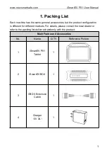
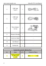
Page 9: ...the product configuration is different for different markets For details please consult the local dealer or refer to the packing list delivered randomly with the product Main Frame and Accessories No...

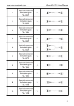
Page 10: ...B Cable Type C 1 6 USB Cable Type B 1 7 Power Adapter 12V 5A 1 8 Password Envelop 1 9 Quick Use Guide 1 10 User Manual 1 11 Packing List 1 Special Connector for Battery Pack No Name Q TY Reference Pic...

Page 11: ...r for battery pack TL 104Y 1 5 Special connector for battery pack TL 105R 1 6 Special connector for battery pack TL 106R 1 7 Special connector for battery pack TL 107R 1 8 Special connector for batter...

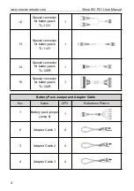
Page 12: ...pecial connector for battery pack TL 114Y 1 14 Special connector for battery pack TL 126R 1 15 Special connector for battery pack TL 130R 1 Battery Pack Jumper and Adapter Cable No Name Q TY Reference...

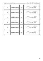
Page 13: ...iSmartEV P01 User Manual www newsmartsafe com 5 5 Adapter Cable 4 4 6 Adapter Cable 5 4 7 Adapter Cable 6 4 8 Adapter Cable 7 4 9 Adapter Cable 8 4 10 Adapter Cable 9 4...

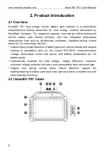
Page 14: ...ulation testing current clamp etc for new energy vehicles Support deep system detection of battery packs of various brands and support reading of parameters such as the current SOC SOH monomer module...

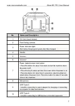
Page 15: ...or about 3 seconds to start the machine when the power is off Press this key to wake up close the screen when the power is on Press the button for more than 3 seconds to select shutdown or restart whe...

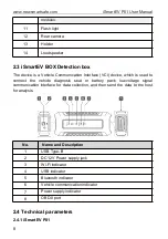
Page 16: ...s used to connect the vehicle diagnosis seat or battery pack low voltage signal communication interface for data collection and then send the data to the host for analysis No Name and Description 1 US...

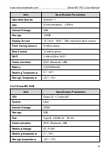
Page 17: ...Camera 8 million pixels Rear Camera 13 million pixels Wi Fi 2 4GHz 5GHz Wi Fi Communication Wi Fi Bluetooth USB Battery 3 8V 9360mAH Working Temperature 0 45 Storage Temperature 20 70 2 4 2 iSmartEV...

Page 18: ...ry power of the device is exhausted you may not be able to turn it on normally when charging This is a normal phenomenon Please charge the device for a period of time and then try to start the device...

Page 19: ...ote Before registration ensure that the network connection to the host is normal and stable On the main interface click Personal Center Login and the following dialog box will pop up If you are a new...

Page 20: ...er and the system will enter the interface of connector activation Enter the product serial number and activation code The product serial number and activation code can be obtained from the password e...

Page 21: ...arge number of software it may take a long time depending on the network speed Please wait patiently B If you have already registered input the user name and password and click Login to enter the acco...

Page 22: ...module needs to be used with iSmartEV FC01 new energy vehicle battery pack detection gun optional which can quickly detect the vehicle battery pack Special Functions Use this function for special func...

Page 23: ...bum screen recording player email and photograph etc as well as system APP 4 1 2 Bottom navigation bar The bottom navigation bar contains the following buttons Icon Name and Function Description Brows...

Page 24: ...establishes a Wi Fi connection At this time the VCI connector icon at the bottom of the host screen lights up and the Wi Fi indicator of the VCI connector is also on 4 2 2 USB communication When the...

Page 25: ...attery pack Danger The personnel who operate the battery pack test must wear protective equipment such as insulation gloves insulation shoes and goggles Operating the battery pack without protection c...

Page 26: ...etection the Fast Charging port detection interface will be displayed after the connection mode is selected as Fast Charging port Detection See Chapter 6 for specific operation A On Board Diagnostics...

Page 27: ...t the vehicle battery pack C Battery pack jumper connection According to the wiring diagram prompted by the software the jump 8 jumper is used to connect the iSmartEV BOX detection BOX and the low vol...

Page 28: ...tection process Report Click to view save the detection report of battery pack Refresh Click to refresh the current data of battery pack Function description Voltage Detection Used to display the volt...

Page 29: ...etermine the fault point Fault Code Detection Used to read the fault code in the current battery pack BMS system Actuation Test Used to test whether the execution components in the system can work pro...

Page 30: ...vehicle so as to help the maintenance personnel quickly determine the battery pack fault 1 On the main interface click Quick Charging Port Detection to enter the quick battery pack detection screen Ma...

Page 31: ...te 1 When testing again the system will automatically connect the detection gun 2 If you need to switch the detection gun please close the previously connected device and search for the connection aga...

Page 32: ...rtEV P01 User Manual www newsmartsafe com 24 6 Click Save to save the quick test report on the host 7 Click Share to generate the two dimensional code and scan the two dimensional code to share the re...

Page 33: ...y identify vehicle information and vehicle detection without manual selection of vehicle type Click Vehicle Detection Intelligent Detection on the main interface to enable the intelligent detection fu...

Page 34: ...that can be tested Confirm Click to enter the next step 3 Select the model and year of the vehicle to be tested for example BYD 2018 E5 Travel version Automatic selection Clicking this item will autom...

Page 35: ...y this will only be displayed if the vehicle testing software supports this function On the screen for selecting test options click Quick Test The system starts to scan each system for fault codes and...

Page 36: ...have been completely cleared after maintenance Note Before performing this function please ensure that The pre maintenance inspection report of the current test vehicle has been saved and Repairs have...

Page 37: ...All test reports are stored in the Main Interface Test Report tab Help Click to view the cause analysis of the fault code Code clearing Click to clear all the fault codes Note For general models plea...

Page 38: ...e Click Read Fault Code on the test function selection page and the screen will display the following detection results Warning Reading a fault code while troubleshooting a vehicle is only a small ste...

Page 39: ...the clearing of the fault code Note For general models please operate in strict accordance with the conventional sequence read the fault code first then clear the fault code in the test run read the...

Page 40: ...nt page Select all data stream options on the current page Select all Select all data stream options Cancel selection Click to cancel all the selected data stream options Confirm Confirm the current o...

Reviews: