background image

16 


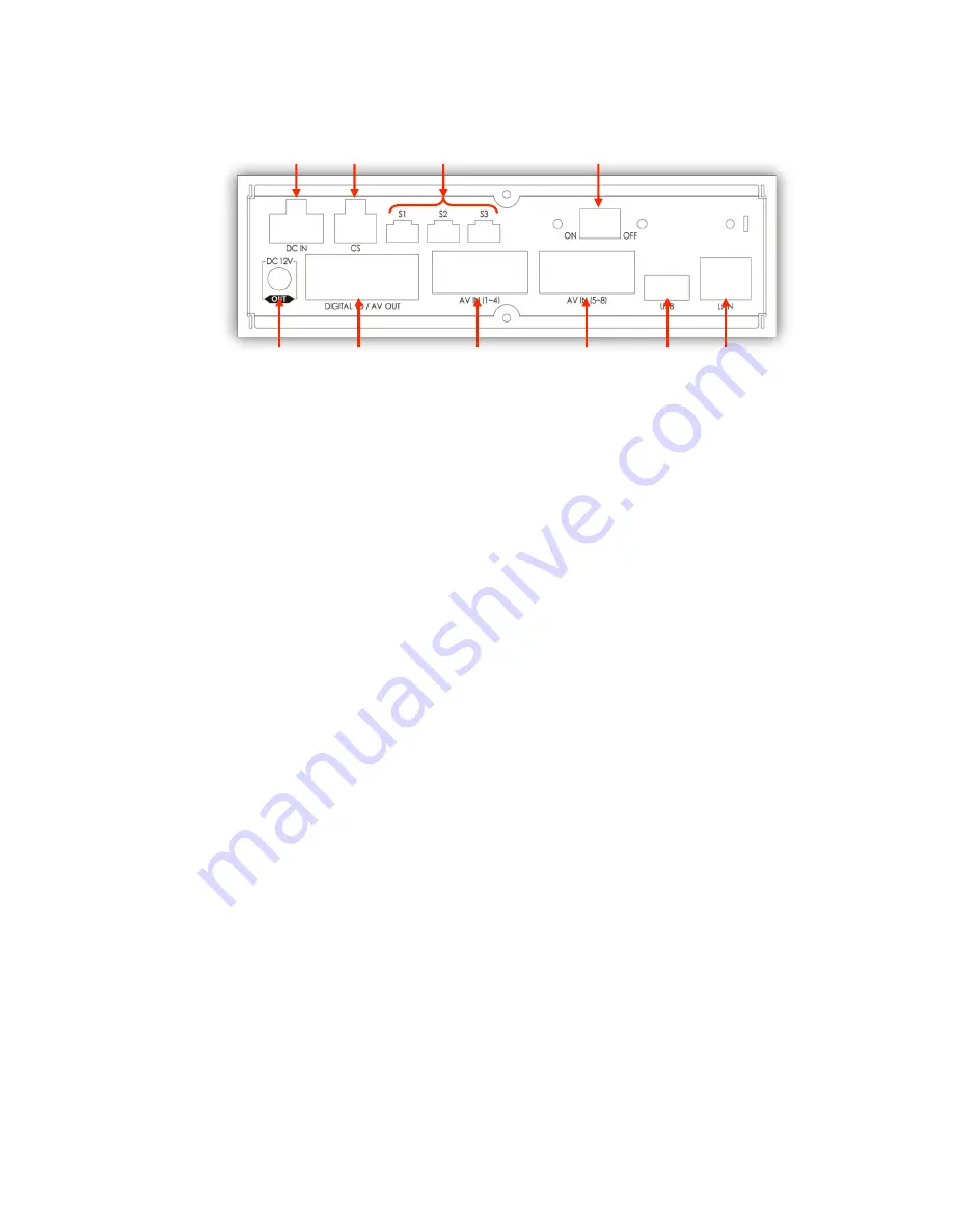
3-2. Rear 


Power Connector 
Use  the  included  power  cable  bundle  for  this  connection,  the  battery  cable 
connects to the battery power and the ACC cable connects to the ignition or 
main power switch. 


Car Signal Connector 
Use the car signal cable bundle for this connection. Connect the appropriate 
car signals to the labeled cables. 


Serial Ports 

Port 1: Connect external device usually used for system maintenance 
Port 2: Connect external device usually used to connect EMS Alert Unit 
Port 3: Connect external device usually allotted for external GPS 


Main Power Switch 


Power out (DC 12V)   


Digital IO / AV out Connector 

Digital Input 1: Allotted for RPM signal 
Digital  Input  2  ~  8:  Connects  to  other  signal  inputs  such  as  panic  switch, 
horn, door open and close, etc. 
Digital Output 1 ~ 2   
Audio / Video Out 


AV In (1~4) Connector 
Cameras 1 ~ 4: Video, audio, and 12 V power supply 


AV In (5~8) Connector 
Cameras 5 ~ 8: Video, audio, and 12 V power supply 


USB connector 
Supports  firmware  up-grade,  set  up  file  upload  /  download,  and  network 
connection 


Ethernet connector 
Supports network connection 


⑤ 

⑥ 

⑦ 

⑧ 

⑨ 

ㅇ 

① 

② 

③ 

④ 

Summary of Contents for SVC400GPS-L

Page 1: ...h the capabilities your new Mobile DVR can provide by reading this manual carefully l Please be careful when using your new device while driving l Your new device may be upgraded with new functions and features periodically please check our website www smartwitness com or with your sales rep to stay updated and maximise your experience ...

Page 2: ...in such cases Software License Agreement Smart Witness and its suppliers grant to the customer a nonexclusive and nontransferable license to use the PC Viewer software in object code form solely on a single central processing unit owned or leased by Customer or otherwise embedded in equipment provided by Smart Witness Customer may make one archival copy of the Software provided Customer affixes to...

Page 3: ...ay 28 3 1 6 DEVICE EXTERNAL DEVICE 29 3 2 Record Settings 31 3 2 1 Record Settings Quality Resolution 32 3 2 2 Record Settings Channel Set Up 33 3 2 3 Record Settings Record Option 34 3 3 SYSTEM Settings 34 3 3 1 SYSTEM DATE TIME LANGUAGE 35 3 3 2 SYSTEM USER MANAGEMENT 36 3 3 1 SYSTEM SERVICE 37 4 Uploading Downloading the Setting File 39 4 1 Upload 39 4 2 Download 39 PC Viewer Software Instructi...

Page 4: ...6 1 Calendar Search 54 6 2 Event Search 54 7 Blur Function 56 8 Data Backup and Printing 58 8 1 Still frame conversion to jpg 58 8 2 Video conversion to avi 59 8 3 Print Image 59 9 Backup and Backup list 61 9 1 Backup 61 9 2 Backup List 61 10 Setting 63 10 1 PC Viewer set up 63 10 2 DVR Configuration 65 10 2 1 Device 66 10 2 2 Record 68 10 2 3 Event 71 10 2 3 1 Motion 71 10 2 3 2 Alarm Input 73 10...

Page 5: ...orage Media 79 12 About 79 12 1 Version Info 79 12 2 Hotkeys 80 Appendix A Shortcut Key list 81 Appendix B Suggested Axis Adjustments by Device Positions 82 Appendix C Recording Time Table 86 Appendix D Specifications 89 ...

Page 6: ...PARTS INSIDE REFER SERVICING TO QUALIFIED SERVICE PERSONNEL WARNING TO PREVENT FIRE OR ELECTRIC SHOCK HAZARD DO NOT EXPOSE THIS APPLIANCE TO RAIN OR MOISTURE CAUTION Connect your vehicle s power cable to the product after starting the vehicle The instant over voltage generated when starting up the vehicle may damage the product if it is already connected CAUTION Install the product where it does n...

Page 7: ... etc 1 If there is an object at the end of the GPS antenna 2 If your vehicle has metallic elements on the windshields 3 If equipment generating electromagnetic waves that interfere with the GPS signal is installed in the vehicle e g other GPS devices such as certain types of wireless activated alarms MP3 CD players etc using GPS 4 If you are using a receiver connected by cable electric interferenc...

Page 8: ...art Number Part Name and Description Image 1 1 SVC400GPS L or SVC800GPS L SVC400GPS L SVC800GPS L Mobile Digital Video Recorder main unit 2 1 Waterproof GPS Module and Case 3 1 Double sided tape use to fasten GPS Module 4 1 Removable SSD HDD case 5 1 Back Cable Cover use to install SVC unit ...

Page 9: ...ys for internal lock turns on device and locks HDD SSD case in the SVC unit 8 Keys for external lock locks main unit s front cover 9 1 or 2 Camera Cable connects 4 cameras each SVC400GPS L comes with one SVC800GPS L comes with two 10 1 Digital IO A V Out 11 1 Power in Cable ...

Page 10: ...10 No Qty Part Number Part Name and Description Image 12 1 Car Signal Cable 13 1 PC Viewer Installation CD or SD card User Guide ...

Page 11: ...ovable Storage SATA I interface 2 5 HDD or SSD External Device USB Host 1 Rear SD Card 1 Front LAN Wire 10 100 bps G Sensor Internal 3 Axis Serial Port 2 1 GPS RS 232C Signal Port 5 Left Right Brake Reverse Speed Input Interface Front Button up down left right enter esc ch search fn s tatus Power Out DC 12V 1 Front 1 Rear Application Language English Japanese Russian Korean Chinese Simplified Trad...

Page 12: ...ight Enter Channel Search Function Esc Status 10ea IR Receiver IR Remote Controller reserve 1ea IO Rear Video Inputs Video NTSC PAL In Camera Power DC 12V 8ea Audio Input Line in 8ea Car Signal Left Right Brake Reverse Speed Pulse 5ea Alarm In 1 4 Voltage off on 5 7 Normal open close 8 RPM 8ea Alarm Out Digital output 2ea Serial Port 1 Debug 1ea Serial Port 2 Tachometer 1ea Serial Port 3 External ...

Page 13: ...tons SER Search data by date using calendar index CH Select single camera view MENU Set up ESC Return to previous screen Direction keys to move selections during set up Change layout of live screening to 9 split screen Change layout of live screening to 4 split screen Press down for 3 seconds to stop EMS data recording and safely eject SD card Note While accessing the menu data may be being record...

Page 14: ...ll fully power off in 1 min and 15 sec The delay time for record off and power off time can be modified using the power board s dipswitch inside the device For more information please consult with your dealer SD Card Slot Plug in SD card to upload and download EMS data SD cards can be inserted at any time but must be safely ejected by pressing for 3 seconds prior to removal After you hear the doub...

Page 15: ...15 Ø Two short beeps will sound when upload is finished One short beep will sound if there is an error Video Out Port Audio Out Port DC 12V Power Out ...

Page 16: ...ernal device usually used to connect EMS Alert Unit Port 3 Connect external device usually allotted for external GPS Main Power Switch Power out DC 12V Digital IO AV out Connector Digital Input 1 Allotted for RPM signal Digital Input 2 8 Connects to other signal inputs such as panic switch horn door open and close etc Digital Output 1 2 Audio Video Out AV In 1 4 Connector Cameras 1 4 Video audio a...

Page 17: ...elow SSD or HDD record status bar Date and time Speed indicator Current speed Speed limit Recording indicators refer to the Live Display Indicators Insert below Note 1 When the device is properly set up and powered on power on and off can be controlled by either the main power switch or the ignition depending on your own connection arrangement 2 At power on the unit will automatically self check I...

Page 18: ...o Standard Displays video Standard either NTSC or PAL Mac Address GPS Displays longitude latitude and speed If there is no GPS value check your location to see if there is any GPS signal reception Alarm In Out Displays digital input 1 7 and digital output 1 2 0 means no signal 1 means there is a signal Speed Pulse Displays speed pulse and speed measured by the vehicle s speed pulse If the speed in...

Page 19: ...ct type 3 MAIN MENU 1 To access Menu press MENU and the default password The password can be changed refer to the below Notice box 2 After typing the password press MENU again and the below screen will show 3 Within Menu there are three directories Device Record and System 4 Use and to change directories 5 Within each directory there are sub directories that can be accessed by pressing and then ME...

Page 20: ...empty no password will be set Repeat this process to confirm Press ESC to return to previous stage and exit MENU Note 1 Not all configurations can be set from the main device please use the PC Viewer if you wish to access the full array of configurations 2 The categories that cannot be changed are shaded in grey ...

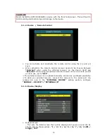
Page 21: ...tions When the subcategory you wish to set up is highlighted in yellow press MENU to enter configuration Ø Press ESC to return to previous screen 3 1 1 Device Camera Ø Move between the set up selections using the arrow keys Ø Channel Select the channel for configuration using the arrow keys Ø Video Turn the selected channel on off using the arrow keys ...

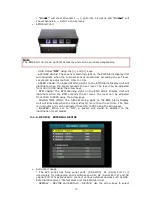
Page 22: ...the correct kind among JIS 4W JIS 2W 3W SAE DIN BNA The Carpulse Standard Value will change with the standard chosen Ø RPM Pulse Type Check the carpulse type standard and use the and keys to set the correct kind among 1 10 Note 1 The channels that are turned off cannot be viewed live nor will it be recorded 2 When there is a recording failure the video loss icon will show on the channel s live scr...

Page 23: ...ration FX Deceleration RX Turn Y Vertical Z trigger levels from 0 1G 1 0G Ø The trigger levels are used as event points when driving data is recorded and are utilized when searching for excessive G sensor changes while accelerating decelerating turning or when in accidents Caution 1 When using an HDD postion the device in an upright positon only 2 The postions and adjustments in REF2 are ONLY for ...

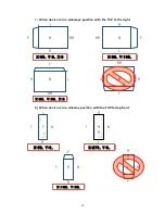
Page 24: ...r T Top B Bottom R Right side L Left side 1 When device is in an upright position Caution 1 When using an HDD postion the device in an upright positon only 2 The postions and adjustments in REF2 are ONLY for when using SSDs T F L R B T F L B RR T F R B RR T L R B RR X 0 Y 0 Z 270 X 0 Y 0 Z 0 X 0 Y 0 Z 90 X 0 Y 0 Z 180 Driving direction ...

Page 25: ...position 3 When device is in a sideway position with the TOP to the left B F R L T B F L T RR B F R T RR B R L T RR X 180 Y 0 X 180 Y 0 Z 0 X 180 Y 0 X 180 Y 0 T F RR L R T F RR L R T F RR L R T F RR L R X 270 Y 90 X 270 Y 0 Z 0 X 270 Y 180 ...

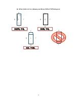
Page 26: ...th the TOP to the right 5 When device is in a sideway position with the TOP facing front B F RR R L B F RR R L B F RR R L B F RR R L X 90 Y 90 Z 0 X 90 Y 0 Z 0 X 90 Y 180 B T R L R R T B R L F T B R R R F T B L R R F X 180 Y 90 X 90 Y 0 X 270 Y 0 ...

Page 27: ...27 6 When device is in a sideway position with the TOP facing rear T B L R R R B T L R F B T L R R F B TOP R R R F X 0 Y 90 X 270 Y 0 Z 270 X 90 Y 0 Z 90 ...

Page 28: ... receiver is an optional accessory and can be purchased separately To utilize an external receiver connect the receiver to the serial port 2 marked S2 and in the EXTERNAL DEVICE setting section configure SERIAL2 DEVICE to EXTERNAL IR 3 1 5 Device Display Ø Default Screen This sets the initial screen that will be displayed at power on and can be chosen among these options 1 2 3 4 5 6 7 8 2 2 1 2 2 ...

Page 29: ...vel The level can be adjusted from 0000 to 9999 using the arrow keys IDLING TIME MIN The Idling Warning Light on the EMS Alarm Display Unit will illuminate when the driver idles for more than the set time The time is in minutes and can be adjusted from 000 to 999 using the arrow keys BUZZER When set to ON a buzzer will sound in addition to the illumination for all alarms 3 1 6 DEVICE EXTERNAL DEVI...

Page 30: ...EED RPM and SIGNAL Depending on what data is being drawn from the tachometer GPS SPEED RPM and SIGNAL can be activated by using the arrow keys Note 1 To avoid repetitive device settings the device selected for SERIAL2 DEVICE will not be available for selection for SERIAL3 DEVICE and vice versa 2 Since there are only two available serial ports only two external devices can be used at the same time ...

Page 31: ...us screen Ø The total recording time depends on the size of the data storage device and record settings Please refer to Appendix C for the recording timetable Note 1 The times on the recording timetable are approximations Since The SVC400 800GPS L uses the H 264 standard for video compression depending on the recorded video the size of the data will differ Therefore the recording times on the reco...

Page 32: ...rrow keys If N A is selected there will be no pre recordings in case of an event Ø POST REC TIME Sets the amount of recording time after an event is triggered Select between 0 sec N A 10 sec 30 sec 1 min 5 min 10 min 30 min and 1 hour using the arrow keys If N A is selected recording will stop immediately after the event has ended i e there will be no post recordings in case of an event Note PRE R...

Page 33: ...POST REC TIME are set the recording will include these periods Event setting can only be done through the PC Viewer Please refer to section 10 2 3 If set to Normal Event in normal conditions recording will be at 1 ONE frame per second FPS but in an event it will record at the set frames per second Ø FPS Frames per Second Possible FPS will differ based on the resolution and Video standard PAL or NT...

Page 34: ...orded data will not be overwritten i e recording will stop after the SSD or HDD is full 3 3 SYSTEM Settings Ø Important configurations such as date language password format default settings can be set here Note 1 Since the total number of frames change with resolution if the resolution is changed the total number of frames will change and the FPS will need to be re set To avoid redundant operation...

Page 35: ...as PM 02 30 if set to 24H time will be displayed as 14 30 Ø TIMEZONE The time zone needs to be set accurately if synchronizing automatically to GPS time If automatic GPS time synchronization is not used this setting is not required Ø DST Daylight Savings Time Activate if you daylight savings time is in effect Ø TIME SYNC Sets the time when the device should synchronize with the GPS time Select bet...

Page 36: ...ata Ø USER ID The user ID is read from the SD card and can only be set using the EDA software When the SD card with the user ID is plugged in the user ID will automatically be read and displayed Ø PASSWORD An 8 digit password can be set using the arrow keys The factory set password is the sequence and Press menu to change the password The password sequence will be needed to be typed twice before a...

Page 37: ...older Caution 1 Please backup all important data before formatting as all data will be lost when the data storage medium is formatted 2 Format all new HDD or SSD with the main unit as explained here before use 3 Formatting with your PC and not the main unit may not work and may even cause damage 4 The use of HDD SSD or SD Cards other than those supplied by Smart Witness will invalidate the warrant...

Page 38: ...ually goes to the SD card unless it is specifically chosen Ø CONFIGURATION Press MEMU to reset to factory default Use the arrow keys to select YES and press MEMU again to confirm Ø VIDEO STANDARD Select which the video standard for your country NTSC PAL Caution Do not disconnect the device while upgrade is in progress as it may damage the product If this happens please contact your dealer Caution ...

Page 39: ...mplete you will hear two short beeps and the progress bar will close automatically 4 2 Download Ø The configuration can also be downloaded Insert a SD card or USB memory stick and press both Fn and together While downloading you will hear a sequence of three beeps until complete When downloading is complete you will hear two short beeps When ejecting the SD card press down on the key for two secon...

Page 40: ...d audio data may be converted into an AVI file for your use 1 System Requirements For the PC Viewer to operate properly the following system requirements need to be met 1 1 Hardware Ø CPU Intel Core 2 Duo 2Ghz or higher Ø Main Memory 1G or larger Ø VGA Memory 256M Ø HDD free space 120 MBytes 1 2 Software OS Windows XP Windows Vista Windows 7 Display Resolution 1024X768 Language English Japanese Ko...

Page 41: ...Programs and DVRViewer Ø If you check the Create a desktop icon option during the installation the below icon will be created on your desktop SmartWitness Execution Icon 3 PC Viewer Software Description After connecting the units removable HDD or SSD cartridge to your PC and using a SATA connection cable that can be purchased separately double click the PC ViewerExecution Icon The below PC Viewer ...

Page 42: ...42 3 1 PC Viewer Main Screen Control Bar Video Playback Screen Signal and Alarm Display Bar Playback Control Bar and Interval Selection Bar ...

Page 43: ...43 3 1 1 PC Viewer Control Buttons ...

Page 44: ...44 3 1 2 Control Buttons and Indicators ...

Page 45: ...ns Normal Event Other sub options from the left bottom corner The dates that have recorded video data for that option will be filtered and are highlighted in blue Choose the date you wish to check The chosen date will be highlighted in yellow Caution 1 Only use the SATA to USB adaptor provided with the SVC400 800GPS L unit 2 For some PCs the HDD or SSD may not be recognized and even may casue dama...

Page 46: ...pre set speed limit Video Loss Data with video loss Ø When a date is selected the hours from 0 24 with recorded data will be highlighted in orange for each camera and when the hour is selected the minutes from 0 60 with recorded data will be highlighted in orange for each camera Choose the minute you wish to start your search The selected hour and minutes will be highlighted in blue Ø Click the Se...

Page 47: ...slots that are highlighted in orange and by sliding the time slide bar on the bottom for more precise changes Refer to section 3 1 2 for more detailed description of the control buttons Ø You can change the date by clicking the calendar search button on the tool bar It will take you back to the initial search screen ...

Page 48: ...t you wish to use The screen can be split into 2 3 4 5 5 6 8 9 sections Select Layout Options Ø Example The 5 section layout is as below 5 Section Layout Ø To view a channel in more detail select a channel and double click The screen will change into a single channel view layout with the selected channel showing If you double click again the layout will change back to its original arrangement 4 Se...

Page 49: ...dow Zoom Choose from 1x 2x 4x 8x The zoom will only be applied to the view that the arrow cursor was over Mirror Mode The view will be flipped to reverse left and right Camera Choose from channels 1 8 This will relocate the selected channel to the location that the arrow cursor was pointing to Mosaic Choose to enable the pre set blur function to the current view and or back up Refer to chapter 7 f...

Page 50: ...Information button to view the below Sensor Information screen Ø The default setting only displays the G sensor graphs but other information may be added by checking the boxes in the upper part of the screen as below G sensor X axis red Y axis green Z axis blue based on the positioning of the main unit is shown with the data reference point zero point calibrated and positive shocks as and negative...

Page 51: ...51 measured speed is displayed in grey RPM Displayed in purple All triggers signals and alarms are displayed on the bottom of the screen with the grey bar meaning the trigger is activated ...

Page 52: ...ows driving blue and idling grey The second bar shows the speed where white means within both the permitted speed and eco speed limit green means above eco speed but within permitted speed limit and red means above the legal speed limit The last bar shows the state of the engine where white means the engine is off blue means it is running properly within the pre set RPM limit and red means over ac...

Page 53: ...the in pink and the location of the vehicle with an orange arrow 5 4 PC Viewer Display Ø The Smart Witness PC Viewer is composed of a main screen sensor information screen driving analysis screen and the tracking screen These screens can be displayed independently and their location and size changed to improve use and management of data ...

Page 54: ...gnals alarms speed and RPM you can find incidents and events quicker than monitoring the vast amounts of video and audio recordings Ø Click the Event Search button to access the event search screen Ø Select the search range Ø Check the components G sensor signals alarms speed etc that you wish to filter and click Search A list of data files that match the filter criteria will show up as below ...

Page 55: ...55 Ø Double click the data you wish to inspect or select the data and click the GotoVideo button The data will be accessed and ready to play back ...

Page 56: ...set up screen will pop up as below Ø Using the scroll down select the camera you wish to set up Ø On the selected camera view blur out the area you wish to protect by left clicking on the sections You can select multiple areas Ø You can also unselect selected areas by right clicking the blurred areas Ø To select all or clear all click on the Select all or UnSelect All buttons on the bottom respect...

Page 57: ...57 Blurred Image ...

Page 58: ...uts you wish to save Ø Check all the information you wish to include from the options shown The selected information will be imprinted on the image itself Ø If you check Apply Mosaic the images will include the blurs Ø Choose the folder you wish to save the image to and click Start Still frames from all selected cameras at the paused instance will be saved as jpg files in the folder The default fo...

Page 59: ... changed Ø Select the frame rate FPS from 1 to 30 you wish to use For the most natural video stream use 30 FPS Ø Check the supplementary information you wish to include in the video The selected the information will show up as text on the video itself Ø Choose the folder you wish to save the AVI file and type a file name The default folder is My Documents SmartWitness SVC400GPS L AVI and the defau...

Page 60: ... report and any comments about the situation or other reminders Ø If the Apply Mosaic box is checked the pre set blur effect will be applied Ø When you click OK a preview of the report like the one below will be pop up Ø After checking all the information press Print to print the report ...

Page 61: ...process Ø Input all the information you wish to include in the back up file including DVR ID User ID title and comments Ø Select the folder where you wish to save the backup file The default folder is My Documents SmartWitness SVC400GPS L BACKUP Ø To ease management of the backup files choose a category and type in or later select from the previously logged types Ø Press Start to create the backup...

Page 62: ...the report type by scrolling down the options Ø The files are listed showing the Date Time DVR ID User ID Title Ø Check the box next to the file you wish to play back click OK The below file list will pop up Double click the file and video files will show on the PC Viewer as below Ø The controls are the same as when playing back from the HDD or SSD ...

Page 63: ...4H or 12H AM PM Date format Choose from YYYY MM DD or MM DD YYYY or DD MM YYYY Audio gain Choose from 0 5x 4 0x Any value above 1 0x increases the volume while any value less than 0 5x reduces it Save Layout If you wish to save a certain layout of the various windows Set up the windows as you wish before entering the setting process Once the layout is set up select default and press Save Layout Th...

Page 64: ...ain Map and Info will lock into place and will change as one window Soften Image If checked the image will be softened when viewed Ø Maxvalue setting Information Window The graph scales for the Sensor Information Window will be modified according to the settings For example if the Speed G sensor and RPM is to 60 1G and 2000 respectively it will look like below Ø DVR Config Refer to the next sectio...

Page 65: ...ructions section 4 1 To upload the settings you configured with the PC Viewer Ø Click the Settings Button and when the settings window pops up Click the NEW button under DVR Config Ø Select the SVC model you have SVC400GPS L or SVC800GPS L and click OK Ø If you wish to modify a previous setting plug in the SD card or USB that has the previous settings and click OPEN Select the settings file and do...

Page 66: ...ong 1 2 3 4 5 6 7 8 2 2 1 2 2 2 3 3 2 2 1 is cameras 1 4 split into 4 and 2 2 2 is cameras 5 8 split into 4 Apply Tachometer Data The SVC is compatible with various Tacho devices If using data drawn from a Tacho check the data here Remote Controller N A if remote controller is not used Internal IR if the reader on the main unit is used External IR if an external reader is connected and used Car Pu...

Page 67: ...more sensitive than 1 0G External Device S2 S3 The unit has 3 serial ports of which S1 is reserved for maintenance and S2 and S3 can be used to connect other devices Depending on what device is connected to the ports select from N A GPS External IR EMS Alert Unit TACHO DONGSUN TACHO DTE Leave as N A if not used Baud rate Check the specification of the device you are connecting and select from 4800...

Page 68: ...n record real time 30 FPS for all cameras Each channel can be set from 1 to 30 FPS FPS used shows the current used frames total frames that can be used depending on resolution Type The recording type is realted to the SD EventRecord Type on the right You need to set this prior to selecting the Type here To Note The SD EventRecord and Dual Record settings decide what data and at what frequency the ...

Page 69: ...ing at 1 FPS will be on the HDD or SSD but when there is an Event defined in the Event tab the recording will switch to the set FPS Audio Check if you wish to include audio for this channel VideoType Select from NTSC or PAL Resolution Select from D1 704 480 HD1 704 240 CIF 352 240 Quality Select from Normal High Super EventRecord Pre Select from N A or 1 sec 5 sec If N A is selected there will be ...

Page 70: ...on video data Pre This sets the pre recording time on the SD card You can select from 0 N A to 15 sec Post This sets the post recording time on the SD card You can select from 0 N A to 15 sec Dual Record If this box is checked all video will be recorded on both the SSD or HDD and the SD card On the SD card regardless of the FPS setting only 1 FPS will be recorded per channel Overwrite If this box ...

Page 71: ...sh to use Sensitivity Select from 1 5 where 1 is dull and 5 is sensitive Set Grid The default is the whole camera view but a region can be set as below The region can be set by using the left button on the mouse Multiple regions can be set If you wish to clear a set region use the right button on the mouse To select the whole area or to unselect us the appropriate buttons on the bottom Record CH S...

Page 72: ...n output alarm such as a siren can be used Select from N A 0 1 5 10 20 30 30 50 60 and seconds LiveoutCH Duration If you have a monitor connected a video output can be used Select how you wish the display layout should be from 1 2 3 4 5 6 7 8 2 2 1 2 2 2 3 3 If multiple motions are detected the unit will follow the Liveout Priority setting Refer to section 10 2 3 5 Duration Select how long you wis...

Page 73: ...ra s that you wish to record when the motion sensor is triggered For example you can choose camera 1 and 2 to record when motion is detected in camera 1 The Record CH boxes are Channels 1 to 8 starting from the left to the right Only the channels that are checked in the Device Menu can be selected AlmOut1 2 An output alarm such as a siren can be used Select from N A 0 1 5 10 20 30 30 50 60 and sec...

Page 74: ...cord CH boxes are Channels 1 to 8 starting from the left to the right Only the channels that are checked in the Device Menu can be selected AlmOut1 2 An output alarm such as a siren can be used Select from N A 0 1 5 10 20 30 30 50 60 and seconds LiveoutCH Duration If you have a monitor connected a video output can be used Select how you wish the display layout should be from 1 2 3 4 5 6 7 8 2 2 1 ...

Page 75: ...as that you wish to record when the motion sensor is triggered For example you can choose camera 1 and 2 to record when motion is detected in camera 1 The Record CH boxes are Channels 1 to 8 starting from the left to the right Only the channels that are checked in the Device Menu can be selected AlmOut1 2 An output alarm such as a siren can be used Select from N A 0 1 5 10 20 30 30 50 60 and secon...

Page 76: ... will have priority Liveout Priority This sets the priority for the 11 types of display that the SVC offers 1 has the highest priority and 11 has the lowest For example in the above setting if channel 3 and channel 4 are both triggered at the same time channel 3 has priority and the monitor will show channel 3 ...

Page 77: ...ing this box and selecting when to synchronize from Boot On 0 23 O clock If Boot On is selected the unit will synchronize its time with the GPS whenever it boots and if this is not possible as soon as the reception of the GPS is recovered after booting If a time is selected the unit will synchronize its time with the GPS at the specified time If this is not possible as soon as the reception of the...

Page 78: ...a types and this sets the maximum storage capacity for EMS data only Max count The SD card can hold multiple data types and this sets the maximum number of EMS data EMS Alarm Device Check the box if you are using the EMS Alarm Device G Sensor Set the trigger point for g sensor values If checked the g sensor light will illuminate when this alarm is triggered Overspeed Set the trigger point for spee...

Page 79: ... remove data storage media button Ø A list with all SSDs or HDDs connected with the PC will pop up Ø Select the data storage media you wish to safely remove 12 About This shows the PC software version DVR Firmware version copyright info and hotkeys 12 1 Version Info Ø Click the About button to see the below pop up Ø You can check the PC Viewer version and DVR version info ...

Page 80: ...s You can utilize the hotkeys to control the PC Viewer more efficiently Ø Click the About button to see the below pop up Ø Scroll down to view all the shortcut keys Ø Refer to Appendix A for all default shortcut keys ...

Page 81: ...ackward forward 5 seconds backward forward 30 seconds backward forward 1 minutes backward forward Mute Audio Channels 1 8 Volume up down Capture Screen Still frame Capture Screen video start and pause Space P B 1 2 3 4 5 6 7 8 Left Right Alt Left Alt Right Ctrl Left Ctrl Right Shift Left Shift Right M Alt 1 Alt 8 Up Down Ctrl J Ctrl A Layout 1 camera Full screen Minimize screen 1 1 1 2 2x2 1 4 1 S...

Page 82: ...ide L Left side 1 When device is in an upright position 2 When device is in an upside down position Caution ONLY for when using SSD as data storage HDD users MUST postion the device upright T F L R B T F L B RR T F R B RR T L R B RR X 0 Y 0 Z 270 X 0 Y 0 Z 0 X 0 Y 0 Z 90 X 0 Y 0 Z 180 Driving direction ...

Page 83: ... is in a sideway position with the TOP to the left B F R L T B F L T RR B F R T RR B R L T RR X 180 Y 0 X 180 Y 0 Z 0 X 180 Y 0 X 180 Y 0 T F RR L R T F RR L R T F RR L R T F RR L R X 270 Y 90 X 270 Y 0 Z 0 X 270 Y 180 ...

Page 84: ...th the TOP to the right 5 When device is in a sideway position with the TOP facing front B F RR R L B F RR R L B F RR R L B F RR R L X 90 Y 90 Z 0 X 90 Y 0 Z 0 X 90 Y 180 B T R L R R T B R L F T B R R R F T B L R R F X 180 Y 90 X 90 Y 0 X 270 Y 0 ...

Page 85: ...85 6 When device is in a sideway position with the TOP facing rear T B L R R R B T L R F B T L R R F B TOP R R R F X 0 Y 90 X 270 Y 0 Z 270 X 90 Y 0 Z 90 ...

Page 86: ...86 Appendix C Recording Time Table ...

Page 87: ...87 ...

Page 88: ...88 ...

Page 89: ...age SATA I interface 2 5 HDD or SSD Key Lock External Device USB Host 1 Rear SD Card 1 Front LAN Wire 10 100 bps G Sensor Internal 3 Axis Serial Port RS 232C 2EA GPS Port External GPS 1EA Signal 5 Left Right Brake Reverse Speed Pulse Input Interface Front Button up down left right enter esc ch search fn status Power Out DC 12V 1 Front 1 Rear Language English Japanese Russian Korean Chinese Simplif...

Page 90: ...ght Enter Channel Search Function Esc Status 10ea IR Receiver IR Remote Controller reserve 1ea IO Rear Video Input Video NTSC PAL In Camera Power DC 12V 8ea Audio Input Line in 8ea Car Signal Left Right Brake Reverse Speed Pulse 5ea Alarm In 1 4 Voltage off on 5 7 Normal open close 8 RPM 8ea Alarm Out Digital output 2ea Serial Port 1 Debug 1ea Serial Port 2 Tachometer 1ea Serial Port 3 External GP...

Reviews: