9
SVC400L - Installation Instructions
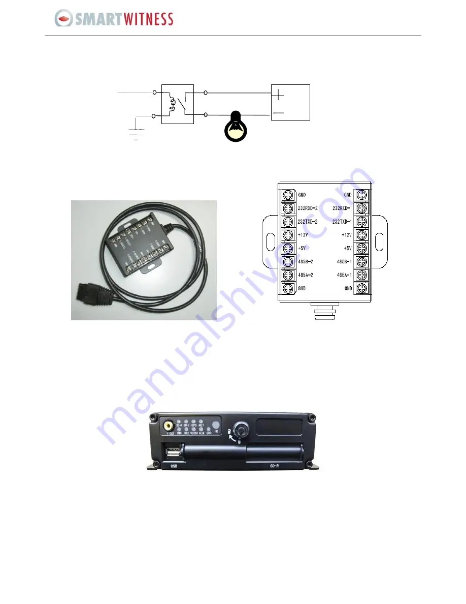
All alarm outputs are PWL outputs, drive ability is 200MA, and the voltage is +12V, if you need more than that, please connect to
an external relay. An alarm output photoelectric wiring diagram is as follows:
7.3 Specifications for 485 and 232 serial ports
There are two 485 serial ports and two 232 serial ports, the functions are the same.
These serial ports can connect to accessories purchased from Shenzhen Streaming Video Technology, such as the inertia sensor
(acceleration), control panel, PTZ, station announcement, and the card reader etc.
Please Note:
485A means 485+, 485B means 485-
8. WORKING STATUS
Check all the LEDs when the device starts up:
POWER is ON means the power is normal
ERR is ON means there is no SD card or there are some other hardware errors
NET is ON means the net module is normal
VIDEO LOSS is ON indicates video loss
The SVA400L may be malfunctioning if there is no live view when all the LEDs are ON. Please contact technical support
for additional support.
24V
Alarm output


