P 03
w w w . s m a x . c o m . t w
Chapter I.
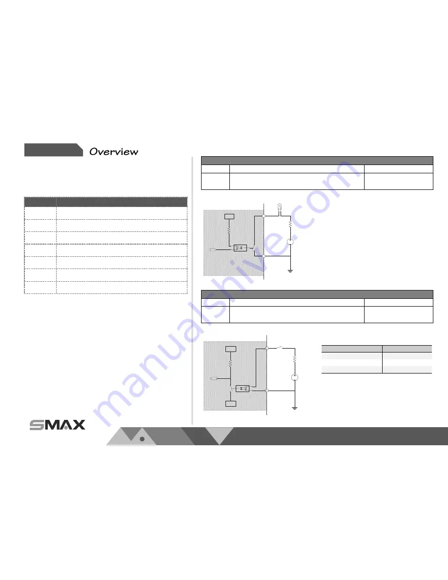
Digital Input
Pin
Notes
Specifications
Trigger is “Off”, DO connect to GND
Trigger is “On”, DO is floating
Max load:
30mA,30VDC
Trigger
H
CAMERA
DO
GND
GND
Power
RL
Digital Output
Pin
Notes
Specifications
DI is floating, trigger is “high”
DI is high, trigger is “low”
Max current input:
30mA
Trigger
DI
GND
GND
H
L
SW
Power
RL
CAMERA
Suggested Component Value:
Power(VDC)
RL(Ω)
3.3V
100Ω
5V
200Ω
12V
510Ω
Item
Description
1
RS485-
2
RS485+
3
GND
4
DO
5
DI 1
6
DI 2
7
GND
1.2. Physical Description
1.2.2.
Digital Input (DI) & Digital Output (D0)


