Version 6.00
Date of editing: 16.09.2022
r.
Page 5 of 30
Technical documentation
KWP-L
4.
TECHNICAL DESCRIPTION
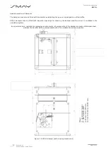
The KWP-LS dampers (with a spring mechanism) and the KWPLE dampers (with an electric spring return actuator)
consist of a housing of a rectangular cross-section, a moving, single-axis isolating baffle and an actuating mechanism
with a release device.
The damper housing and its interacting elements are made of galvanized steel sheet. Connection flanges are on both
ends of the housing for easy connection between the duct and the damper.
There are intumescent seals on the outer and inner surfaces of the housing, in the place of perforation, around the
closed isolating baffle. Their characteristic feature is that their volume increases at high temperatures, tightly filling all
leaks between the baffle and the body.
The isolating baffle of the damper is made of calcium-silicate board, and a rubber seal is installed on its perimeter,
ensuring the damper integrity at ambient temperature.
The KWP-LS damper is provided with a spring mechanism comprising, ea. an actuating spring, a manual release
device and a thermal fuse
with a nominal triggering temperature of 70 ± 5°C. When the damper is being opened with
a key, the actuating spring is being tensioned. The baffle is kept in the open position by the manual release device,
blocked with a thermal fuse. The damper is automatically closed as a result of triggering the thermal fuse. The damage
to the thermal fuse automatically rotates the isolating baffle (to the closed position). The movement of the baffle is
limited by two buffers.
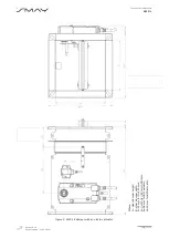
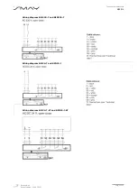
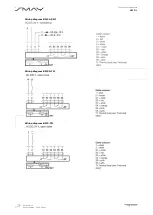
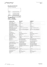
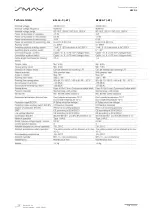
The KWP-LE damper is provided with an electric spring return actuator BFL, BFN or BF series manufactured by
BELIMO, and the BAT or BAE thermal fuse
(72°C, 95°C optionally), constituting damper’s drive system supplied by the
230 V AC or 24 V AC/DC voltage. After the voltage has been supplied, the actuator rotates the baffle to the open
position. The baffle is closed due to voltage loss or when the thermal fuse is activated (the return spring in the
actuator closes the baffle by returning to the non-stressed position). During normal operation of the system, the KWP-
LS and KWP-LE dampers are in the open position. If a fire breaks out, the damper baffle rotates to the closed position.
The permissible air velocity in a connection duct for the KWP-LE dampers with an actuator is 12 m/s and 8 m/s for the
KWP-LS dampers with a spring mechanism.
The range of dampers covers the following dimensions: a clear damper width from 160 to 800 mm (10 mm intervals
from the width 200 mm) and a clear damper height from 200 to 500 mm (10 mm intervals). The primary type series
of damper dimensions, including actuators, is provided in the table below.
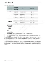
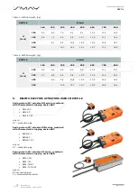
Table 2. Type series of damper dimensions, including used actuators
B [mm]
H
[mm]
160
200
300
400
500
600
700
800
200
BFL
300
BFL
400
BFL
BFN
500
BFL
BFN
BFL actuators are used for the damper clear area of ≤ 0,24
[m
2
].
BFN actuators are used for the damper clear area of >0,24 [m
2
].
BF actuators are used for all series fire dampers.
Depending on the actuation system used, the dampers are marked as follows:
▪
KWP-LS
- the dampers with a spring mechanism,
▪
KWP-LE
- the dampers with an electric spring return actuator,
The length of KWP-L dampers is L=350 mm.


