6-3. Wiring of control signal input part (reset, hold and bank selection)
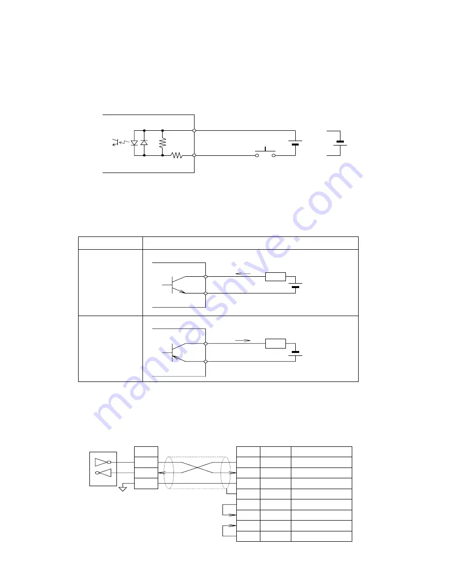
Each control signal shall be inputted in a circuit using a transistor that allows current flow
of 15 mA or more, or a circuit of contact output. Input time for reset signal shall be 10 ms
or longer. Bank selection and hold are active only in signal inputting.
COM is common for each signal input as well as for NPN and PNP input types. Use a
power of 24VDC or 12VDC and connect to DC
-
for PNP input and to DC
+
for NPN input.
CEU5 control signal input part
(
)
C ontrol signal input
C O M
1kΩ
2.2kΩ
(reset, hold and bank
selection)
O r
Power (24VD C or 12VD C )
6-4. Wiring of output part (preset output and cylinder stop output)
The following shows the wiring for preset output (OUT 1 through 5) and cylinder stop
output (S. STOP) with two output types: NPN and PNP.
Model Wiring
CEU5
CEU5B
CEU5-D
CEU5B-D
NPN transistor (open collector output)
L o a d
C O M
O U T
P o w e r
(3 0 V D C o r le s s )
5 0 m A o r
CEU5P
CEU5PB
CEU5P-D
CEU5PB-D
PNP transistor (open collector output)
Load
CO M
O UT
Power
(30VDC or less)
(50 m A or less)
6-5. Wiring of RS-232C
Electric feature: complying with EIA RS-232C
Terminal block signal name
S D
R D
S G
S D
R D
S G
E q u i v a l e n t t o
L T 1 1 8 1
F G
S y m b o l
S y m b o l
C o u n t e r s i d e
H o s t c o m p u t e r s i d e
R S - 2 3 2 C
R S - 2 3 2 C
I n p u t
O u t p u t
T r a n s m i t t e d d a t a
R e c e i v e d d a t a
S i g n a l g r o u n d
S i g n a l
d i r e c t i o n
S i g n a l
-
F r a m e g r o u n d
-
R S
R e q u e s t t o s e n d
O u t p u t
C S
C l e a r t o s e n d
I n p u t
D R
D a t a s e t r e a d y
I n p u t
E R
D a t a t e r m i n a l r e a d y
O u t p u t
-
12
-


