background image


- 11 - 


I.D.4mm. This nipple fits both nylon tube and urethane tube. Connection process of nylon or 
urethane tube is as follows.


1) Remove the box nut, pass nylon tube or urethane tube through the nut. 
2) Insert the tube into the fitting body. 

3) Fasten the nut to the body.


6) When the cylinder direction is switched, select an appropriate solenoid valve for 

direction control from SMC stock. 3-Port solenoid valve is used for switching the 
valve.


2-4. Lubrication 

Warning


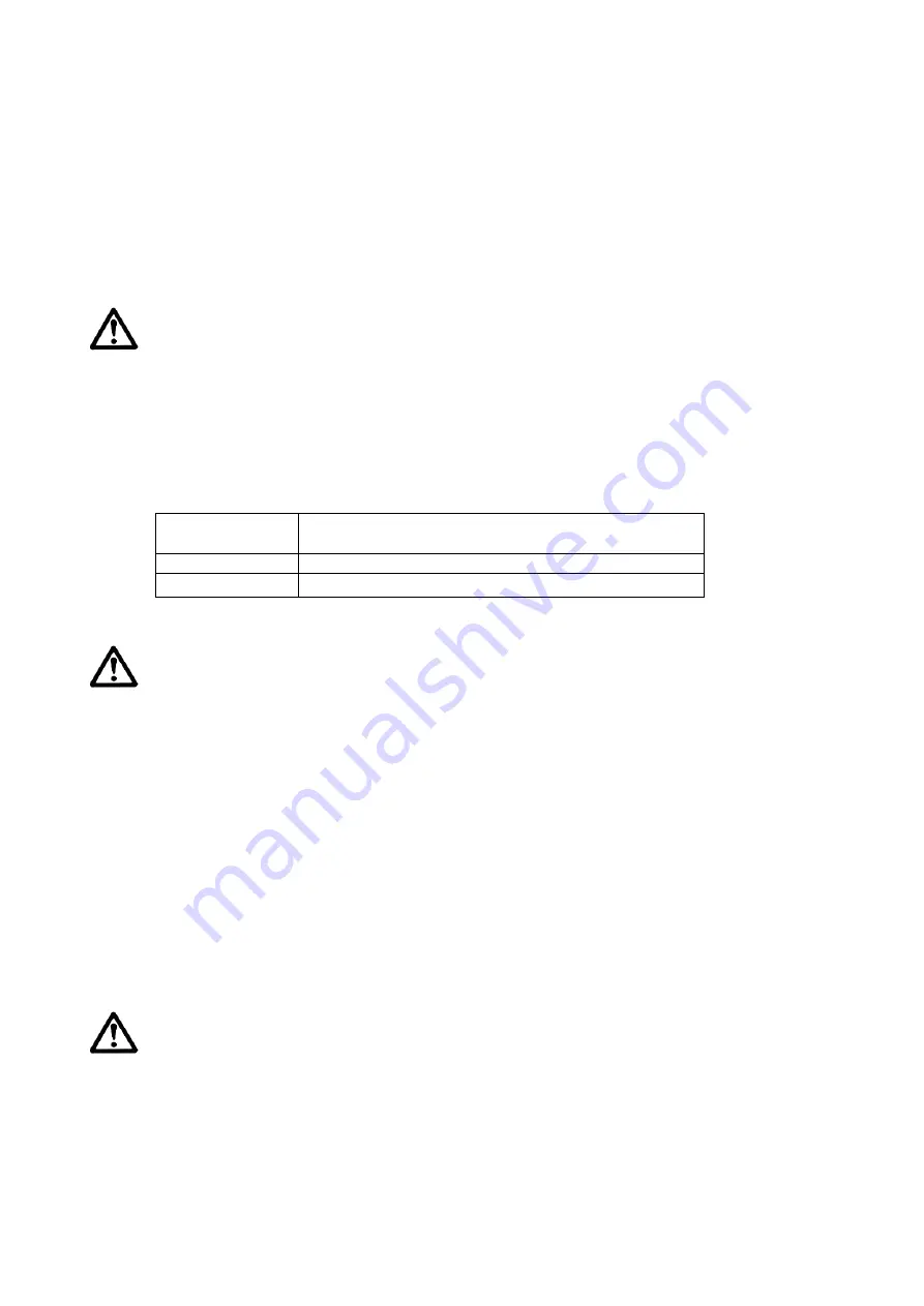
1) Lubricating non-lube type cylinders 

These cylinders have been lubricated for life at the factory and can be used without 

any further lubrication. However, in the event that it is lubricated additionally, be sure 

to use the following one. Stopping lubrication later may lead to malfunctions because 

the new lubricant will cancel out the original lubricant. Therefore, lubrication must be 

continued once it has been started. 

Bore size 

  (mm)   

Kind of lubrication oil 

Polyalphaolefin oil or equivalent oil 

6

10

16 

class 1 turbine oil (with no additives) ISO VG32 


2-5. Air supply 

Warning


1) Type of fluids 

Please consult with SMC when using the product in applications other than compressed air. 

2) When there is a large amount of drainage 

Compressed air containing a large amount of drainage can cause the malfunction of pneumatic 

equipment. An air dryer or water separator should be installed upstream from filters. 

3) Drain flushing 

If condensation in the drain bowl is not emptied on a regular basis, the bowl will overflow and 
allow the condensation to enter the compressed air lines. This causes the malfunction of 
pneumatic equipment. If the drain bowl is difficult to check and remove, the installation of a 
drain bowl with an auto drain option is recommended. 


For compressed air quality, refer to the SMC Best Pneumatics No. 6 catalog. 

4) Use clean air. 

Do not use compressed air that contains chemicals, synthetic oils that include organic 

solvents, salt, corrosive gases, etc., as it can cause damage or malfunction. 


Caution


1) When extremely dry air is used as the fluid, degradation of the lubrication 

properties inside the equipment may occur, resulting in reduced reliability 
(or reduced service life) of the equipment. Please consult with SMC. 

2) Install an air filter.


Install an air filter upstream near the valve. Select an air filter with a filtration size of 5 μm 

or smaller. 

3) Take measures to ensure air quality, such as by installing an aftercooler, air dryer, 

or water separator. 

Summary of Contents for CJP Series

Page 1: ...Doc no CJP OM0207Q A PRODUCT NAME Pin Cylinder Single Acting Spring Return MODEL Series Product Number CJP 4 16 Z ...

Page 2: ...on force 1 4 Allowable kinetic energy 1 5 Allowable lateral load 2 Mounting Installation P6 2 1 Design Selection 2 2 Mounting 2 3 Piping 2 4 Lubrication 2 5 Air supply 2 6 Operating environment 2 7 Maintenance 3 Construction Description P13 4 Dimensions P14 4 1 Dimensions 4 2 Dimensions of accessories 5 Troubleshooting P16 ...

Page 3: ...nt failure when configuring the equipment 2 Only personnel with appropriate training should operate machinery and equipment The product specified here may become unsafe if handled incorrectly The assembly operation and maintenance of machines or equipment including our products must be performed by an operator who is appropriately trained and experienced 3 Do not service or attempt to remove produ...

Page 4: ... of the product 3 Prior to using SMC products please read and understand the warranty terms and disclaimers noted in the specified catalog for the particular products 2 Vacuum pads are excluded from this 1 year warranty A vacuum pad is a consumable part so it is warranted for a year after it is delivered Also even within the warranty period the wear of a product due to the use of the vacuum pad or...

Page 5: ...ype Embedded type Accessory Standard equipment Standard equipment Mounting nut 2 Rod end nut 2 Mounting nut 1 Gasket 1 Rod end nut 2 Option Hose nipple 4 is excluded When rod end is threaded The Value in the brackets shows quantity For details about the hose nipple refer to page 9 1 2 Theoretical output N Bore size mm Operating direction Operating pressure MPa 0 3 0 5 0 7 4 OUT 0 97 3 48 6 00 IN 1...

Page 6: ...ad mass and maximum driving speeds Bore size mm 4 6 10 16 Piston speed mm sec 50 to 500 Allowable kinetic energy J 0 5X10 3 3X10 3 8X10 3 19X10 3 1 5 Allowable lateral load Strictly observe the limiting range of lateral load on a piston rod Refer to the below graph If this product is used beyond the limits it may shorten the machine life or cause damage Maximum speed V mm sec Load mass kg Stroke S...

Page 7: ...damage the equipment 6 Avoid synchronized operation using cylinders only Even if multiple pneumatic cylinders are initially set to the same speed their speeds may vary due to changes in operating conditions Therefore avoid designs where a single load is moved by synchronizing multiple cylinder operations 7 Consider the action of the cylinder when restarting after an emergency stop Devise a safe de...

Page 8: ...necting When not properly aligned the rod and tube may be twisted and damage may be caused due to wear on certain areas such as the inner tube surface bushings rod surface or seals 2 When an external guide is used connect the rod end and the load in such a way that there is no interference at any point within the stroke 3 Do not scratch or gouge the sliding parts of the cylinder tube piston rod et...

Page 9: ... 8 5 6 3 5 M8X1 0 6 5 3 10 20 16 5 14 15 28 24 5 22 6 5 16 12 5 10 3 5 M10X1 0 8 5 3 10 23 19 5 17 15 30 26 5 24 10 5 17 13 5 10 5 3 5 M15X1 5 12 4 10 23 5 20 17 15 30 5 27 24 16 5 19 14 5 11 5 4 5 M22X1 5 19 5 10 25 20 5 17 5 15 31 5 27 24 Note E and F should be machined in a concentric manner When embedded Machining dimensions for mounting Air Air O ring Sealed with O ring ...

Page 10: ...lant tape When screwing piping or fittings into ports ensure that chips from the pipe threads or sealing material do not enter the piping Also if sealant tape is used leave 1 5 to 2 thread ridges exposed at the end of the threads 4 The following fittings are recommended for this cylinder connection However there may be case where the piston speed exceeds 500 mm sec even with the recommended fittin...

Page 11: ... sure to provide a speed controller after adjusting it to 500 mm sec or less 5 Piping connection to the cylinder A hose nipple consists of two parts a fitting body and a box nut There are two sizes one is for O D 4mm I D 2 5mm tube and the other is for O D 6mm Urethane tube Nylon tube Box nut Fitting body Gasket To cylinder port or elbow joint ...

Page 12: ...tions other than compressed air 2 When there is a large amount of drainage Compressed air containing a large amount of drainage can cause the malfunction of pneumatic equipment An air dryer or water separator should be installed upstream from filters 3 Drain flushing If condensation in the drain bowl is not emptied on a regular basis the bowl will overflow and allow the condensation to enter the c...

Page 13: ... shock 4 Do not mount the product in locations where it is exposed to radiant heat 5 In dusty locations or where water or oil etc splash on the equipment take suitable measures to protect the rod 6 A decrease in the base oil of grease may be accelerated by the properties of the compressed air used in pneumatic equipment the external environment operating conditions etc and the resulting drop in lu...

Page 14: ... 13 3 Construction Description ...

Page 15: ...haust port Exhaust port Without rod end thread Without rod end thread Hose nipple Mounting dimensions of CJ 5H 6 denotes the dimensions of CJ 5H 4 Embedded type Without rod end thread Without rod end thread Exhaust port Exhaust port Boresize mm Boresize mm ...

Page 16: ... 15 4 2 Accessory bracket dimensions ...

Page 17: ...g speed The speed is lower than specified piston speed Use within specifications 1 1 Improper pneumatic circuit design The system construction is not suitable Select adequate size of tube fitting directional control valve speed controller etc 2 2 2 3 A part is damaged Breakage of piston tube 1 The speed is too high due to insufficient adjustment of the speed controller 2 The kinetic energy exceeds...

Page 18: ... ku Tokyo 101 0021 JAPAN Tel 81 3 5207 8249 Fax 81 3 5298 5362 URL https www smcworld com Note Specifications are subject to change without prior notice and any obligation on the part of the manufacturer 2019 SMC Corporation All Rights Reserve ...

Reviews: