background image

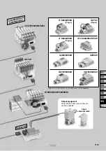
CC-Link

DeviceNet™

PROFIBUS DP

3 master stations
3 manifold

1 node
1 manifold

1 node
1 manifold

Compatible protocol

Conventional SI unit model

CC-Link

DeviceNet™

PROFIBUS DP

3 master stations
4 manifold/4-input unit

1 node
4 manifold/4-input unit

1 node
4 manifold/4-input unit

Compatible protocol

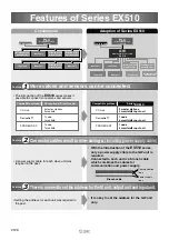
Series 

EX510

•  The introduction of the 

EX510

 series makes it 

possible to connect more valves and sensors.

•  A power supply cable for each slave unit was 

required in the past. 

•  With the introduction of the 

EX510

 series, 

only a power supply cable to the GW unit is 
required.
Connected to each unit is a branch cable 
which combines the cables for 
communication and power supply.  

Branch cable

Communication 

lines

Power supply 

lines

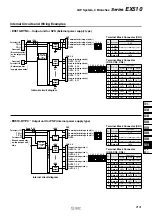
• Setting the address for each unit was required in 

the past. 

•  It is okay to set the address for the GW unit 

only. 

Including SI unit

manifold valve

Input unit

Including SI unit

manifold valve

PLC

Programmable logic

controller 

Input unit

Input unit

Including SI unit

manifold valve

Input unit

Including SI unit

manifold valve

PLC

Programmable logic

controller 

Including SI unit

manifold valve

Including SI unit

manifold valve

GW

Serial transmission system

EX510

Input unit

Input unit

Output unit

Input unit

Input unit

Including SI unit

manifold valve

Power supply

Power supply

Features of Series EX510

Conventional 

Adoption of Series EX510

Feature

Connector cables result in wire-savings. (including power supply cable)

Feature

More valves and sensors can be connected.

There is no need to set the address for the SI unit, output unit and input unit. 

Feature

2126

Summary of Contents for EX510-GDN1

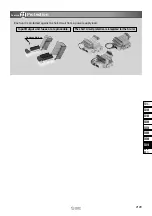
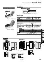
Page 1: ...h Flow switch Pressure switch Input device Input units with covers The product is shown without a cover The product is shown without a cover Two 2 wire auto switches can be connected to a single connector connectors GW unit Compatible communication network Compatible communication network Series EX510 GW System 4 Branches 2124 ...

Page 2: ...1000 2000 SZ3000 SY3000 5000 Plug in S0700 Plug in 2 port solenoid valve Output equipment Valve indicator light relay buzzer etc can be connected Including SI unit manifold valve Output unit Note SY SYJ SQ SZ S0700 VQ VQZ are not yet UL compatible 2125 EX12 EX140 EX180 EX260 EX250 EX600 EX500 EX510 PCA EX EX510 ...

Page 3: ...cation lines Power supply lines Setting the address for each unit was required in the past It is okay to set the address for the GW unit only Including SI unit manifold valve Input unit Including SI unit manifold valve PLC Programmable logic controller Input unit Input unit Including SI unit manifold valve Input unit Including SI unit manifold valve PLC Programmable logic controller Including SI u...

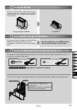
Page 4: ...s The SI unit which connects output devices such as a solenoid valve has a compact design compared with a existing model Compactness volume ratio more than 60 60 8 30 64 Existing model Series EX120 Series EX510 70 19 6 31 No need to strip the wire Only pliers are required for clamping Branch connector e con connector Lead wire Flat head screwdriver Torque control crimping work is unnecessary Screw...

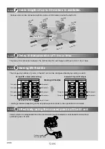
Page 5: ...n be configured flexibly by setting a switch Setting is different depending on the respective protocol Refer to the specifications for details 64 inputs 64 outputs Initial setting Example 32 inputs 32 outputs Making I O flexible Side view of the GW unit are parts in use SI unit Cable assembly for an output entry Various units can be connected within a radius of 20 meters around the GW unit Input u...

Page 6: ...ort circuit from a power supply load Replaceable fuse Protection Feature Input Output unit fuses are replaceable The short circuit protection is integrated for the SI unit 2129 EX12 EX140 EX180 EX260 EX250 EX600 EX500 EX510 PCA EX EX510 ...

Page 7: ... Not provided Communication connector 1 pc Power suppy connector 2 pcs Communication connector 1 pc Power suppy connector 2 pcs Terminating resistor 1 pc Provided 96 96 3 stations remote device station Possible to change depending on the switch setting 64 64 Possible to change depending on the switch setting 24 VDC 10 5 100 mA or less single GW unit 64 inputs 16 inputs x 4 branches Possible to cha...

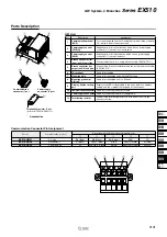
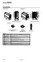
Page 8: ...setting part Applications 1 2 3 4 5 6 7 8 9 10 11 12 For connecting with a network using the communication connector 0 which is part of the accessories Supplies power for output devices which have a power supply connector 1 such as a solenoid valve Supplies power for input devices which have a power supply connector 1 such as a sensor Connects the SI unit manifold valves etc using the branch cable...

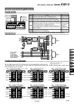
Page 9: ...g switch is changed When the transmission is working properly Light is turned on Light is turned on Blinks at 0 4 second intervals Light is turned off Input unit Input device is connected and will illuminate when communication is working properly Series EX510 Address setting Mode setting Setting of occupied stations HOLD CLR setting Not used Communication speed setting DC DC converter insulated Po...

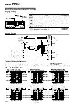
Page 10: ... to D When COM A to D are receiving data When COM A to D are not receiving data Light is turned on Light is turned off Input unit Input device is connected and will illuminate when communication is working properly GW System 4 Branches Series EX510 Address setting Number of input settings Number of output settings Communication speed setting HOLD CLR setting HW SW setting DC DC converter insulated...

Page 11: ...ower supply voltage is supplied as specified The output power supply voltage is not supplied as specified Light is turned on Light is turned off RUN When the input and the power for the Gateway is being supplied When the input and the power for the Gateway is not being supplied Light is turned on Light is turned off DIA When the extended diagnostic information is available When the extended diagno...

Page 12: ...tandards Enclosure Operating temperature range Operating humidity range Withstand voltage Insulation resistance NPN sensor input PNP sensor input 16 inputs 24 VDC 0 2 A per point 0 9 A per unit 100 mA Input unit internal parts 5 6 kΩ Approx 4 mA Green LED illuminated when turned ON IP10 10 to 50 C 35 to 85 RH with no condensation 500 VAC for 1 min between whole external terminal and FG 10 MΩ or mo...

Page 13: ...iption Branch connector on the input unit side LED for power supply LED for display Fuse e con connector Mounting hole Mounting groove for DIN rail Cover Applications 1 2 3 4 5 6 7 8 For press fitting the branch connector o to the branch cable EX510 FC for connecting with the GW unit Light ON Power supply ON Normal state Light OFF Power supply OFF state Light ON When the input for sensor signal is...

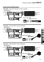
Page 14: ... the input unit side EX510 DXP1 Input unit for PNP 1 connector 2 input type Branch connector on the input unit side DC DC converter not insulated For input 24 V RD RD For input 0 V CN0 24 IN0 IN1 24 24 IN2 IN3 24 24 IN4 IN5 24 24 IN6 IN7 24 24 IN8 IN9 24 24 IN10 IN11 24 24 IN12 IN13 24 24 IN14 IN15 24 CN1 CN2 CN3 CN4 CN5 CN6 CN7 For sensor 24 V Input w Input q For sensor 24 V 1 2 3 4 1 DC 2 Input ...

Page 15: ...15 NC 0 1 2 3 4 Internal Circuits and Wiring Examples Series EX510 For input 24 V RD RD For input 0 V For sensor 24 V Input w Input q For sensor 0 V For sensor 24 V NC Input w For sensor 0 V Wiring example D M9N 3 wire type auto switch NPN output DC DC converter not insulated CN0 2 4 14 CN1 3 5 15 1 DC 2 NC 3 DC 4 Input Brown Blue Black For input 24 V RD RD For input 0 V For sensor 24 V Input w In...

Page 16: ...4 VDC 16 outputs Spring type 0 08 to 1 5 mm2 AWG16 to 28 Built in short circuit protection 50 mA or less inside a unit IP10 10 to 50 C 35 to 85 RH with no condensation 500 VAC for 1 min between whole external terminal and FG 10 MΩ or more 500 VDC between whole external terminal and FG CE marking UL CSA 130 g including accessories Internal power supply supplied by GW unit External power supply supp...

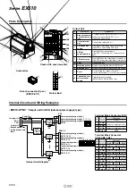
Page 17: ...nal box Mounting hole Mounting groove Terminal box for external power supply Applications 1 2 3 4 5 6 7 8 9 10 For press fitting the branch connector 1 to the branch cable EX510 FC for connecting with GW unit Used for mounting the unit on the DIN rail Light ON Power supply ON Normal state Light OFF Power supply OFF state Light ON When receiving data Light OFF When there is no communication data Li...

Page 18: ...UT13 OUT12 OUT11 Terminal Block Connector CN2 CN3 CN4 COM Output COM Output COM Output COM Output COM Output 1 2 3 4 5 6 7 8 9 10 EX510 DYN4 Output unit for NPN External power supply type Internal Circuits and Wiring Examples EX510 DYP3 Output unit for PNP Internal power supply type Internal circuit diagram Common for driving a load Common for driving a load Common for driving a load OUT0 Common f...

Page 19: ...d under the condition with 5 valves turned on simultaneously Operating current per point for a valve 10 5 W 24 V 0 44 A Meets the output unit load current requirement 1 Therefore the total current of the output unit is 10 5 W 24 V x 5 pcs 2 2 A Only the external power supply type can meet the requirement 2 The internal power supply type cannot be used Based on the requirment 3 The total current fo...

Page 20: ...s Rated load voltage Max load current Enclosure Current consumption Standards Weight Environment EX510 S001 S002 Sink NPN Positive common EX510 S101 S102 Source PNP Negative common Specifications How to Order Sink NPN Positive common Source PNP Negative common 0 1 Output specifications Mounting specifications SI Unit Nil A B C Screw mounting Mounting on DIN rail vertically Mounting on DIN rail hor...

Page 21: ... purchased SI Unit No Description Branch connector on the SI side unit LED for power supply LED for communications Mounting hole Connector for connecting a load Mounting bracket Connector lock pin insertion part Coversion cable assembly Applications 1 2 3 4 5 6 7 8 For press fitting the branch connector o to the branch cable EX510 FC for connecting with the GW unit The cable assembly used for conn...

Page 22: ...N7 For output 24 V TD TD For output 0 V PNP output PNP output 24 V 24 V q w e r r e w q r e w q OUT0 For load 0 V For load 0 V OUT1 OUT14 For load 0 V For load 0 V OUT15 Connector for connecting a load DC DC converter not insulated PNP output PNP output For output 24 V TD TD For output 0 V 24 V 24 V OUT0 OUT1 OUT2 OUT3 For load 0 V For load 0 V Not connected Not connected OUT15 OUT14 PNP output 24...

Page 23: ...ic conductance C dm3 s bar representative value Series Piping with One touch fittings Metric size Inch size Thread piping VQZ1000 VQZ2000 VQZ3000 Applicable cylinder size reference ø40 ø63 ø80 Port size for A B ports SYJ Sonic conductance C dm3 s bar representative value Series Piping with One touch fittings Metric size Inch size Thread piping SYJ3000 SYJ5000 SYJ7000 Applicable cylinder size refer...

Page 24: ...ctance C dm3 s bar representative value Series Piping with One touch fittings Metric size Inch size Thread piping Applicable cylinder size reference Port size for A B ports Sonic conductance C dm3 s bar representative value Series Piping with One touch fittings Metric size Inch size Applicable cylinder size reference Port size for A B ports Sonic conductance C dm3 s bar representative value Series...

Page 25: ... input unit and the output unit respectively 01 02 05 10 20 60 10 16 0 40 L Brown 24 V Black Communications White Communications Blue 0 V Reference AWG18 Electrical specifications 1000 VAC 1 minute Leak current 1 mA or less Rated voltage Rated current Contact resistance Withstand voltage 24 VDC Max 5 0 A 20 mΩ or less Note Branch cable length is a maximum of 20 m Use the cable by cutting it into l...

Page 26: ...e may be pulled out if the pulling force is 12 N or more Nil S Q None For Series SY SYJ For Series VQ VQZ Note SMC part no 1 pc Orange Red Yellow Blue Green 0 6 to 0 9 0 9 to 1 0 1 0 to 1 15 1 15 to 1 35 1 35 to 1 60 0 1 to 0 5 AWG26 to 20 Cover color Compliant wire diameter ø Nominal cross sectional area mm2 Tyco Electronics Japan G K part no SMC part no 1 pc Red Yellow Orange Green Blue Gray 0 8...

Page 27: ...ld VV5QZ15 SA06C6 1 unit VQZ1150 5LO1 4 units VQZ1250 5LO1 2 units i SY series manifold SS5Y3 42 02 C6 1 unit SY3140 5LOZ 2 units o Cable assembly for output entry EX510 VW10S 1 pc 0 Output unit EX510 DYN3 1 unit 1 2 port solenoid valve VX2120 02 5GS1 1 pc Two branch connectors are attached to the manifold including the SI unit and two are attached to the input unit and the output unit respectivel...

Page 28: ... a fire malfunction or breakdown in the units and connecting devices Check the specifications before handling 3 Establish a backup system beforehand which employs fail safe concepts such as multiple equipment and devices to prevent breakage or malfunction of this product 4 Provide an external emergency stop circuit that will immediately stop an operation and cut off the power supply 5 When using f...

Page 29: ...ble gas explosive gas or corrosive gas Use in such an atmosphere is likely to cause a fire explosion or corrosion This reduced wiring system is not explosion proof 4 Do not use this product in places where there are cyclic temperature changes In case that the cyclic temperature is beyond normal tempera ture changes the internal unit is likely to be adversely effected 5 Do not use this product in p...

Reviews: