background image

11

10

Specifications

Basic specifications

Protocol
Bus Interface

PROFIBUS DP V0
EIA RS-485

Rated voltage

Power supply
voltage

24 VDC
Power supply for input and controlling GW: 24 VDC ±10%
Power supply for output: 24 VDC+10%/-5%

(Warning for voltage drop is given at approx. 20 V)

Rated current

Input/ output
point

Power supply for input and controlling GW: Max. 4.1 A
(Inside GW unit: 0.1 A, Input unit: 4 A)
Power supply for output: Max. 6 A

Input point: Max. 64/ Output point: Max. 64
(Changeable by switch settings)

Higher-level bus

Communication speed

Max. wiring length 

Freeze function

Available

9.6 kbps

1200 m

19.2 kbps 45.45 kbps 93.75 kbps 187.5 kbps

500 kbps 1500 kbps 3000 kbps 6000 kbps 12000 kbps

1000 m

400 m

200 m

Synchronous function

Available

Address setting range

0 to 125

: Max. wiring length differs depending on the specification of a cable.

The specification of wiring length is based on type A cable.

Number of branches for
input/ output

4 branches for input
4 branches for output

Communication type

Communication protocol: Dedicated for SMC
Communication speed : 750 kbps

Lower level bus

Current for input branch

Max. 1 A per branch

Current for output branch Max. 1.5 A per branch

Branch cable length

At 0.75 A per branch: 20 m or less
At 1.0 A per branch  : 16 m or less
At 1.5 A per branch  : 10 m or less
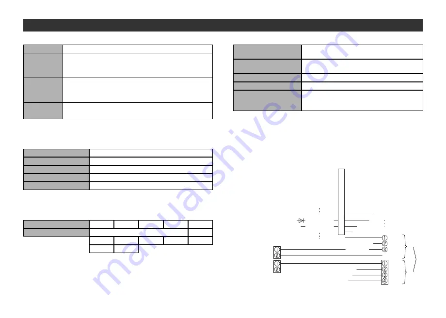
In

te

rn

al

 c

irc

ui

t

DC-DC

Converter

(Insulation)

+24 V

0 V

CO

M

 D

IN

PU

T

O

UT

PU

T

+24 V

RD+

RD-

0 V

+24 V

0 V

Power

supply

for output

Power 

supply

for input

and

controlling

GW

+24 V

TD+

TD-

0 V

Summary of Contents for EX510-GPR1 Series

Page 1: ...tions are subject to change without prior notice and any obligation on the part of the manufacturer 2009 2017 SMC Corporation All Rights Reserved EX OMH0024 C Akihabara UDX 15F 4 14 1 Sotokanda Chiyoda ku Tokyo 101 0021 JAPAN Phone 81 3 5207 8249 Fax 81 3 5298 5362 URL http www smcworld com ...

Page 2: ...tuses that use fieldbus system and have full knowledge of assembly operation and maintenance of such equipment Please read this operation manual carefully and understand it before assembling operating or providing maintenance service to the actuator Thank you for purchasing an SMC fieldbus system EX510 series Please read this manual carefully before operating the product and make sure you understa...

Page 3: ...or damage to the product can result Verify the specifications before use Do not disassemble modify including change of printed circuit board or repair An injury or failure can result IMPORTANT MESSAGES Do not operate in an atmosphere containing flammable or explosive gases Fire or an explosion can result This product is not designed to be explosion proof If using the product in an interlocking cir...

Page 4: ...easures when installing at the following place 1 A place where noise due to static electricity is generated 2 A place where electric field strength is high 3 A place where there is radioactive irradiation 4 A place near power line Do not use the product near by a place where electric surges are generated When a surge generating load such as a relay or solenoid is driven directly use an product wit...

Page 5: ...7 6 Communication connector for PROFIBUS DP 1 piece Power supply connector 2 pieces Accessory ...

Page 6: ...16 PWR V PWR BUS ...

Page 7: ...s 500 kbps 1500 kbps 3000 kbps 6000 kbps 12000 kbps 1000 m 400 m 200 m Synchronous function Available Address setting range 0 to 125 Max wiring length differs depending on the specification of a cable The specification of wiring length is based on type A cable Number of branches for input output 4 branches for input 4 branches for output Communication type Communication protocol Dedicated for SMC ...

Page 8: ...anch cables and be connected with branch connectors SI unit and Input unit have 2 branch connectors for each Pressure welding for branch connector The method of pressure welding for branch connector is explained 1 Components 2 Working procedure Set a branch cable to the cover 1 Set the brown wire of the branch cable so that it comes to the pin 1 2 Meet the cable end to the insulating cap at the co...

Page 9: ... Wiring continued 3 Refer to Drawing 4 about how to connect to the unit VP RxD TxD N DGND RxD TxD P SHIELD Green Red Shield Green Red Shield VP 390 Ω RxD TxD P Data Line Data Line RxD TxD N 220 Ω 390 Ω DGND ...

Page 10: ... connectors Power supply structure consists of 2 systems but it can be used with both single power supply and separate power supply Individual power supply for other units is not necessary Make sure of connection with the designated pin Tighten the connector securely to 0 5 to 0 6 Nm tightening torque ...

Page 11: ...OLD Output is held when a communication error occurs No 9 OFF ON Mode HW Function Set Address with SW1 to 7 SW Address are set by network The setting when shipped from plant is 126 SW1 to 7 are ignored No 10 OFF ON HOLD CLR setting is made available per one point by parameter setting Refer to Operation Manual for detail 0 OFF OFF OFF OFF OFF OFF OFF Setting of the address 126 and 127 are invalid U...

Page 12: ...ED for power supply PWR and the LED for communication COM at SI unit are ON Ensure output branch current does not exceed the specification range Program it after checking the wiring specification of manifold block assembly Check the power for input and controlling GW 24 VDC is supplied Check the input unit indication LED is ON Ensure input branch current does not exceed the specification range Che...

Page 13: ... is correct Check the connecting condition of the terminating resistor Check the number of input output is set correctly 2 DIA LED is lights up Check the power for output 24 VDC is powered at a specified voltage Check the power supply voltage for output is above 20 V Check the input unit is connected after the input port No Item Remedy Disposal Refer to Operation Manual for detail of troubleshooti...

Reviews: