


13
12
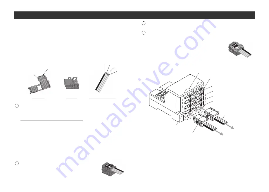
Wiring of branch cables
4 branches for input
4 branches for output
To SI unit
To Input unit
COM D
COM C
COM B
COM A
Branch connector
at cable side
Branch cable
Branch connector
at GW unit side
Insert branch connector on the table side from the bottom
(COM A, B, C, D of branch connector of GW unit side).
EX
510
4
3
2 1
Insulating cap
Brown Black
White
Blue
Cover
Body
Branch cable
Pin no. display
Press fitting
Press the cover to the body with plier etc.
Confirmation
It is completed with a check on 4 latches
engaging.
3
4
Branch wiring
The wiring between each unit should use branch cables, and be
connected with branch connectors.
SI unit and Input unit have 2 branch connectors for each.
Pressure welding for branch connector
The method of pressure welding for branch connector is
explained.
(1)Components
(2)Working procedure
Set a branch cable to the cover.
1) Set the brown wire of the branch
cable so that it comes to the pin #1.
2) Meet the cable end to the insulating
cap at the cover.
3) Fold the cover so that the branch
cable can be put between the
cover.
4) Fix the latch tip by inserting to a hole
for fixing latch.
Note) Check the color of wire written on a
branch connector and the color of
branch cable are same.
Fix to a body tentatively.
Fit 4 latches on a body to 4 ditches on
the cover, and press them until the
latch engages to the level 1.
1
2
Wiring (continued)


