Circulating Fluid Temperature Controller
Thermo-chiller
Dual Channel Refrigerated Thermo-chiller for Lasers
HRL
Series
How to Order
Specifications
HRL
A
20
Pipe thread type
Nil
Rc
F
G (with Rc-G conv
ersion fitting)
N
NPT (with Rc-NPT conv
ersion fitting)
Power supply
20
3-phase 200 VA
C (50 Hz)
3-phase 200 to 230 VA
C (60 Hz)
Cooling method
A
Air-cooled refr
ige
ration
Cooling capacity
CH1
CH2
100
9 kW
1 kW
200
19 kW
1 kW
300
26 kW
1 kW
Model
HRL100-A -20
HRL200-A -20
HRL300-A -20
CH1
CH2
CH1
CH2
CH1
CH2
Cooling method
Air-cooled refrigeration
Refrigerant
R410A (HFC)
Refrigerant charge
[kg]
1.4
2.2
3.0
Control method
PID control
Ambient temperature
[
°
C]
2 to 45
Circulating fluid system
Circulating fluid
CH1: Tap water/CH2: Tap water, Deionized water
∗
1
Set temperature range
[
°
C]
CH1: 15 to 25/CH2: 20 to 40
Cooling capacity
∗
2
[kW]
9
1
∗
8
19
1
∗
8
26
1
∗
8
Heating capacity
∗
3
[kW]
1.5
1
4.5
1
6.5
1
Temperature stability
∗
4
[
°
C]
CH1:
±
0.1/CH2:
±
0.5
Pump
capacity
Rated flow (Outlet)
[L/min] 45 (0.43 MPa
)
10 (0.45 MPa
)
45 (0.45 MPa
)
10 (0.45 MPa
)
125 (0.45 MPa
)
10 (0.45 MPa)
Maximum flow rate
[L/min]
120
16
130
16
180
16
Maximum pump head
[m]
50
49
55
49
68
49
Settable pressure range
∗
5
[MPa]
0.10 to 0.50
0.10 to 0.49
0.10 to 0.55
0.10 to 0.49
0.10 to 0.68
0.10 to 0.49
Minimum operating
fl
ow rate
∗
6
[L/min]
20
2
25
2
40
2
Tank capacity
[L]
42
7
42
7
60
7
Bypass circuit (With valve)
Installed
Electric conductivity setting range
[
μ
S/cm]
—
0.5 to 45.0
—
0.5 to 45.0
—
0.5 to 45.0
Particl
e fi
lter nominal
filtratio
n rating
(
Accessory
)
[
μ
m]
5
Circulating fluid outlet,
circulating fluid return port
CH1: Rc1 (Symbol F: G1, Symbol N: NPT1)
CH2: Rc1/2 (Symbol F: G1/2, Symbol N: NPT1/2)
Tank drain port
CH1: Rc3/4 (Symbol F: G3/4, Symbol N: NPT3/4) CH2: Rc1/2 (Symbol F: G1/2, Symbol N: NPT1/2)
Fluid contact material
(Metal/Resin)
CH1: Stainless steel, Copper (Heat exchanger brazing), Brass, Bronze, Fluororesin, PP, PBT, POM, PU, PC, PVC, EPDM, NBR
CH2: Stainless steel, Alumina ceramic, Carbon, Fluororesin, PP, PBT, POM, PU, PVC, PPS, AS, PS, EPDM, NBR, Ion replacement resi
n
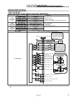
Electrical system
Power supply
3-phase 200 VAC (50 Hz), 3-phase 200 to 230 VAC (60 Hz)
Allowable voltage range
±
10% (No continuous voltage fluctuation)
Earth leakage
breaker
Rated current
[A]
30
40
50
Sensitivity current
[mA]
30
Rated operating current
∗
4
[A]
17
32
41
Rated power consumption
∗
4
[kW(kVA)]
5.4 (5.9)
10.5 (11.0)
13.1 (14.2)
Noise level (Front 1 m/Height 1 m)
∗
4
[dB(A)]
75
75
71
Accessories
Operation Manual (for installation/operation) 2 pcs. (English 1 pc./Japanese 1 pc.), Particle filter set for CH1,
Particle filter set for CH2, Anchor bolt fixing brackets 2 pcs. (including 6 M8 bolts)
∗
7
Weight (dry state)
[kg]
Approx. 222
Approx. 251
Approx. 315
∗
1 Use fluid in condition bel
o
w as the circulating fluid.
Tap water: Standard of The
J
apan Refr
ige
r
ation And Air Conditioning Indust
r
y Association (JRA GL-02-1994)
Deionized water:
Elect
r
ic conductivity 1
μ
S/cm or higher (Elect
ric resistivity 1 M
Ω
·cm or low
er)
∗
2
Ambient temper
ature:
32
°
C,
Circulating
fluid
: Tap water,
Circulating
fluid
temper
ature
: CH1 20
°
C/CH2 25
°
C,
Circulating
fluid
fl
ow rate: Rated
fl
ow,
Pow
er supply
: 200 VAC
∗
3
Ambient temper
ature
: 32
°
C,
Circulating fluid
: Tap water,
Circulating fluid fl
ow rate:
Rated fl
ow,
Pow
er supply
: 200 VAC
∗
4
Ambient temper
ature:
32
°
C,
Circulating
fluid
: Tap water,
Circulating
fluid
temper
ature
: CH1 20
°
C/CH2 25
°
C,
Load
: Same as the
cooling
ca-
pacity,
Circulating fluid fl
ow rate:
Rated fl
ow,
Pow
er supply
: 200 VAC,
Piping length
: Shortest
∗
5
With the pressure control mode
by inverter.
If the pressure control mode is not necessa
ry
, use the fl
o
w control function or the pump output setting function.
∗
6 Fluid fl
ow r
ate to maintain the cooling capacit
y.
If the actual fl
ow rate is lower than this
, adjust the
bypass valve.
∗
7
The anchor bolt fixing b
rack
ets (including 6 M8 bolts) are used
f
or fixing to
wooden skids when pac
kaging the the
rmo-chiller.
No anchor bolt is included.
∗
8 Max. 1.5 kW.
When 1.5 kW is applied, the cooling capacity of CH1 decreases
by 0.5 kW.
100
9


