Circulating Fluid Temperature Controller
Thermo-chiller
Dual Channel Refrigerated Thermo-chiller for Lasers
HRL
Series
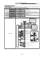
Communication Functions
Wiring of Interface Cable for Serial Communication
Item
Specifications
Connector type
D-sub 9-pin female (socket) type
Configuration of connection
RS-485
Circuit diagram
One thermo-chiller for one host computer, or multiple thermo-chillers for one host computer.
(31 thermo-chillers can be connected at maximum.)
Master
Terminal
resistance
Terminal
resistance
This product
(2nd slave)
This product
(31st slave)
SD+
SD
−
SG
2
SD+
7
SD−
5
SG
This product
(1st slave)
2
SD+
7
SD−
5
SG
2
SD+
7
SD−
5
SG
∗
Do not connect with other pins.
Standards
RS-232C
Circuit diagram
One thermo-chiller for one master
Master
RD
2
SD
3
SG
5
This product
RD
2
SD
3
SG
5
∗
Do not connect with other pins.
To run/stop the product
To change the set value of
circulating fluid temperature
Writing
Circulating fluid temperature
Circulating fluid pressure
Circulating fluid flow rate
Electric conductivity (CH2)
Status of respective parts of the product
(e.g., operation status and content of alarm)
Readout
Serial Communication
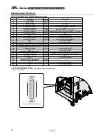
The following operations can be performed by the serial communication RS-232C/RS-485.
D-sub 9-pin female (socket) type
9
6
5
1
18


