Communication Functions
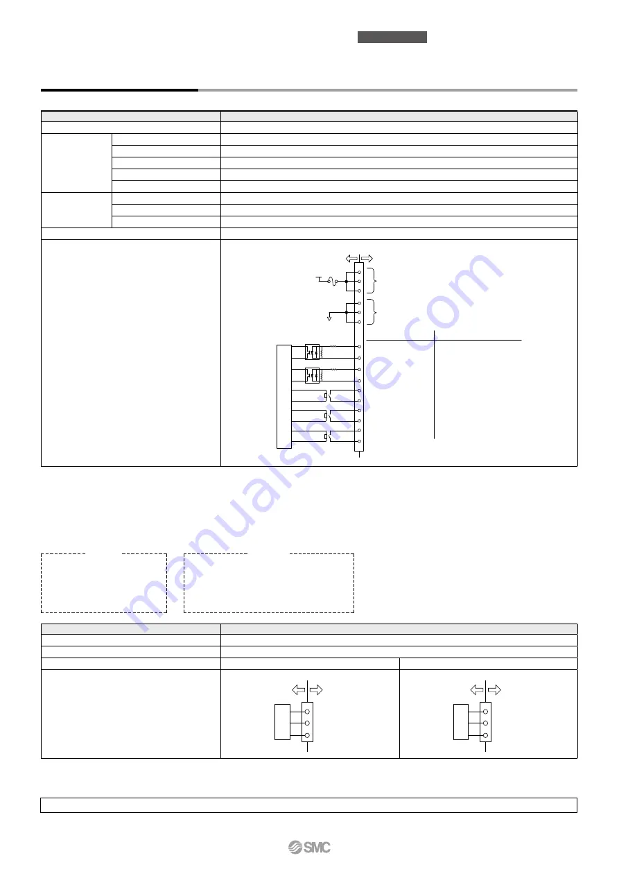
Contact Input/Output
Item
Specifications
Connector type
M3 terminal block
Input signal
Insulation method
Photocoupler
Rated input voltage
24 VDC
Operating voltage range
21.6 to 26.4 VDC
Rated input current
5 mA TYP
Input impedance
4.7 k
W
Contact output
signal
Rated load voltage
48 VAC or less/30 VDC or less
Maximum load current
500 mA AC/DC (Resistance load)
Minimum load current
5 VDC 10 mA
Output voltage
24 VDC
±
10% 500 mA MAX (No inductive load)
Circuit diagram
To the thermo-chiller User’s equipment side
24 VDC
Contact output signal 1
Contact input signal 2
Contact output signal 3
Contact output signal 2
24 VCOM
Contact input signal 1
4.7 k
Ω
4.7 k
Ω
1 k
Ω
1 k
Ω
Alarm status signal output
Run/stop signal input
Operation status signal output
Remote status signal output
—
Signal description
Default setting
∗
1
0
8
1
9
2
10
3
11
4
12
13
14
15
7
5
6
24 VDC output
(500 mA MAX)
∗
2
24 VCOM output
Inter
nal circuit
*
1 The pin numbers and output signals can be set by user. For details, refer to the Operation Manual for communication.
*
2 When using with optional accessories, depending on the accessory, the allowable current of 24 VDC devices will be reduced. Refer to the operation
manual of the optional accessories for details.
Item
Specifications
Connector type
D-sub 9-pin, Female connector (Mounting screw: M2.6 x 0.45)
Protocol
Modicon Modbus compliant/Simple communication protocol
Standards
EIA standard RS-485
EIA standard RS-232C
Circuit diagram
1
9
Internal circuit
To the thermo-chiller User’s equipment side
SD+
SG
SD−
5
2
3
5
To the thermo-chiller User’s equipment side
RD
SD
SG
Internal circuit
*
The terminal resistance of RS-485 (120
W
) can be switched by the operation display panel. For details, refer to the Operation Manual for communication.
Do not connect other than in the way shown above, as it can result in failure.
Serial Communication
The serial communication (RS-485/RS-232C) enables the following items to be written and read out.
For details, refer to the Operation Manual for communication.
Writing
Run/Stop
Circulating fluid temperature
setting (SV)
Please download the Operation Manual via our website, https://www.smcworld.com
Readout
Circulating fluid present temperature
Circulating fluid discharge pressure
Status information
Alarm occurrence information
4
Thermo-chiller
Standard Type
HRS200
Series


