4 Operation
4-10
Lock Operation Delay Time
Model
Voltage
Lock Release Time (ms)
Lock Applied Time (ms)
LECYU2-V5, V7, V8
24 VDC
60
100
LECYU2-V9
80
100
Note: The above operation delay time is an example when the power supply is turned ON and OFF on the DC side.
Be sure to evaluate the above times on the actual equipment before using the application.
(1) Wiring Example
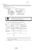
Use the lock signal (/BK) and the lock power supply to form a lock ON/OFF circuit. The following diagram
shows a standard wiring example.
The timing can be easily set using the lock signal (/BK).
BK-R Y: Lock control relay
24 VDC power supply is not included.
DRIVER
Lock
Summary of Contents for LECYU Series
Page 30: ...1 Outline 1 9 1 4 3 Three phase 200 V LECYU2 V9 Models ...
Page 65: ...3 Wiring and Connection 3 11 3 Wiring Example with DC Power Supply Input DRIVER ...
Page 92: ...3 Wiring and Connection 3 38 External Dimensions Units mm 1 FN Type by Schaffner EMC Inc ...
Page 93: ...3 Wiring and Connection 3 39 2 FN Type ...
Page 143: ...4 Operation 4 44 ...


