3 Wiring and Connection
3-25
3.5 Wiring MECHATROLINK-III Communications
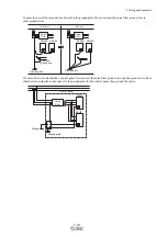
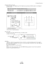
The following diagram shows an example of connections between a PC or PLC...etc and a DRIVER using
MECHATROLINK-III communications cables (CN6A, CN6B).
Note 1. The length of the cable between stations (L1, L2 ... Ln) must be 75 m maximum.
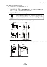
For removing the MECHATROLINK-III communications cable connectors from the DRIVER, refer to the following
procedure.
Slide the lock injector of the connector to the DRIVER side to unlock and remove the MECHATROLINK-III communications
cable connectors.
Note: The MECHATROLINK-III communications cable connector may be damaged if it is removed without being unlocking.
1. Slide the lock injector to
the DRIVER side.
2. Remove the connector while the lock
injector is slid to the DRIVER side.
DRIVER
PLC
Note 1
Note 1
Summary of Contents for LECYU Series
Page 30: ...1 Outline 1 9 1 4 3 Three phase 200 V LECYU2 V9 Models ...
Page 65: ...3 Wiring and Connection 3 11 3 Wiring Example with DC Power Supply Input DRIVER ...
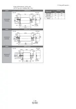
Page 92: ...3 Wiring and Connection 3 38 External Dimensions Units mm 1 FN Type by Schaffner EMC Inc ...
Page 93: ...3 Wiring and Connection 3 39 2 FN Type ...
Page 143: ...4 Operation 4 44 ...


