
4
Pumping Technology
Air Venting
ELECTRICAL CONNECTION AND DIRECTION OF ROTATION
Motors should always be connected, through a suitable starter, to the mains supply.
Ensure that the electrical supply available agrees with the motor details shown on the nameplate.
Connection details are shown inside the terminal box cover. Refer to the motor data plate to check for
star/delta connection. If the pump is supplied with an inverter fitted, then refer to the inverter operating
and maintenance instructions.
STARTING
THE PUMP MUST NOT RUN WITHOUT WATER.
Open suction valve and close discharge valve. Start the pump and slowly open the discharge valve until
fully open.
The pump should never be allowed to operate for long periods in a closed valve condition.
SERVICE/MAINTENANCE
Motor bearings fitted to Omega pumps are “sealed for life” and do not need greasing. The mechanical seal
fitted to this range of pumps should be checked periodically and replaced if necessary.
We recommend that the casing “O” ring (and circlip when fitted) is replaced when a mechanical seal is
changed.
Closed Circuits
Open valves on suction and discharge, allowing water to enter the pump casing.
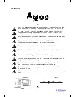
Open the air vent screw on the pump seal chamber (see Fig. 2) and allow all the air to escape.
Close the air vent screw.
Open Circuits - Flooded suction
Proceed as for closed circuits above but with discharge valve closed.
Open Circuits - Suction lift, with foot valve (see Fig. 3).
Break the pipework at a suitable place on the discharge side of the pump.
Open suction and discharge valves and fill pump and pipework to level of break.
Open the air vent screw on the pump seal chamber (see Fig. 2) and allow all the air to escape from this
area. Close the air vent screw.
The water level in the pipe should remain constant, proving that the foot valve is holding.
Reconnect the pipework.
It is very important that the pump is fully vented otherwise the mechanical seal can be damaged.
The direction of rotation of three phase motors can be altered by interchanging any two of the three
main connecting leads.
Single phase motors have the direction of rotation pre-set before despatch.
The direction of rotation is shown with an arrow on the motor cowl and should always be checked after
wiring.
ALL OMEGA RANGE UNITS UP TO OMEGA 10-210 SHOULD ROTATE IN AN ANTI-
CLOCKWISE DIRECTION WHEN VIEWED FROM THE MOTOR NON-DRIVE END.
ALL OMEGA RANGE UNITS OMEGA 12 AND ABOVE SHOULD ROTATE IN A
CLOCKWISE DIRECTION WHEN VIEWED FROM THE MOTOR NON-DRIVE END.