background image


         EN


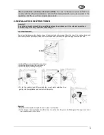
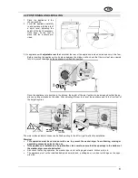
2.3 CONNECTING TO THE WATER SUPPLY 

 
1.     Check  that  the  water  supply  pressure  is  in  the  following  range: 

0,05-0,9MPa

.  With 

higher pressures, use a pressure reducer. 


2.     Connect the 

cold water

 supply hose (

blue

 screw collar) to the cold water tap with ¾ 

gas threaded connector, taking care to tighten firmly to prevent leaks. The water sup-
ply  hose  must  not  be  kinked  or  crushed  and  must  not  be  changed  or  cut.  Threaded 
connections must only be tightened by hand. 


3.     When appliances are supplied with 

hot water

, the intake water temperature must not 

exceed 60°C and the hose with 

red

 screw collar must be connected to the hot water supply tap. 


Warning! 

      If the connection is made to new pipelines, or lines which have been out of use for a long time, allow a con-

siderable amount of water to flow out before connecting the intake hose. This prevents any sand or other dirt 
from fouling the filters installed in the appliance to protect the water intake valves. 


The new intake hose supplied with the appliance must be used, and the old water supply hose must not be 
used. 


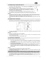
2.4 CONNECTING TO THE DRAIN


1.     Insert the end of the drain hose into a drain pipe having inside diameter of at least 4 cm, at least 50 to 90 cm 

above floor level, or connect it securely (using the plastic fitting on the elbow in the hose) to a sink or bathtub. 


2.    In all cases, check that the end of the drain hose is securely fixed to prevent the repulsive force of the water 

from pushing it out of place. 


Warning! 

      Avoid kinks or restrictions to ensure effective drainage. 

      Any  drain hose  extensions must  be  no  more  than 1 metre  long, must  be  of  the  same diameter  and  must  be 

free from restrictions of all kinds. 


The end of the drain hose must never be submerged in water. 


2.5  ELECTRICAL CONNECTION 


Before connecting the plug to the power socket ensure that: 


1.  The electrical system voltage is the same as that stated on the nameplate on the front of the appliance, 

in the zone visible when the door is open. The rated power supply and the fuses required are specified 
on the nameplate. 

2.  The meter, safety breakers, power supply line and power socket are rated to withstand the maximum lo-

ad required, stated on the nameplate. 

3.  The  power  supply  socket  and  the  plug  fitted  to  the  appliance  are  compatible  without  the  use  of  reduc-

tions, multiple sockets, adapters and extension leads which might cause overheating or scorching. 
If  the  power  supply  socket  is  not  compatible  with  the  plug  supplied,  replace  the  socket  with  one  of  the 
appropriate type. 


Warning 


The power plug must be accessible after the appliance has been installed. 


    It  is  absolutely  essential  to  connect  the  appliance  to  earth. 

Connect  the  plug  to  a socket  with  an  earth 

connection in good working order. 


The manufacturer declines all liability for direct or indirect injury or damage deriving from a non-existent 
or defective earth connection. Correct electrical connection guarantees conditions of maximum safety. 


      This  appliance  is  compliant  with  the  requirements  of  EEC  directive  89/336  of  3.5.89  (including  the  amend-

ment directive 92/31/EEC) concerning the elimination of radio-frequency disturbance. 

      If the power supply lead is damaged, it must only be replaced with an original spare, available from the After-

Sales Service. 


Summary of Contents for LSTA146S

Page 1: ...LAVASCIUGA WASHER DRYER LAVE LINGE S CHANT VOLLWASCHTROCKNER LAVADORA SECADORA LIBRETTO ISTRUZIONI IT INSTRUCTION MANUAL EN MANUEL D INSTRUCTIONS FR GEBRAUCHSANLEITUNG DE MANUAL DE INSTRUCCIONES ES...

Page 2: ...a line through it on the appliance or its packaging indicates that the prod uct must be disposed of separately from other waste at the end of its life cycle The user is thus obliged to consign scrappe...

Page 3: ...r domestic use and is compliant with Directives 72 23 EEC and 89 336 EEC including Directives 92 31 EEC and 93 68 EEC currently in force Read all the instructions in this manual carefully before insta...

Page 4: ...ratures the glass in the door will become very hot Check that all water has been drained from the appliance before opening the door If there is water inside pump it out before opening the door If in d...

Page 5: ...se and maintenance as well as giving useful advice For Great Britain only Warning this appliance must be earthed Fuse replacement If the mains lead of this appliance is fitted with a BS 1363A 13amp fu...

Page 6: ...nts is fixed in place for transport using the screws A on the rear of the washer dryer with the relative plastic spacers B Once the screws have been removed the power supply lead can be used 1 Undo al...

Page 7: ...en the height of the rear feet has to be increased so that the ap pliance no longer stands on the skids After adjusting the rear feet level the appliance and fix the front feet at the height required...

Page 8: ...inage Any drain hose extensions must be no more than 1 metre long must be of the same diameter and must be free from restrictions of all kinds The end of the drain hose must never be submerged in wate...

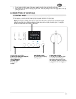
Page 9: ...witching the washer dryer on and off and selecting pro grammes Can be turned in ei ther direction Does not turn whi le programmes are in progress Start Pause button For starting and stopping working c...

Page 10: ...fabrics However some difficult stains such as grass fruit egg blood rust ballpoint pen etc should be dealt with before washing Depending on the type of fabric there are a large number of commercial st...

Page 11: ...tives etc e g treatment products The additives are added to the washing tank automatically during the final rinse The main wash detergent compartment has a tang allowing the use of liquid detergent To...

Page 12: ...doses recommended by the detergent producer 4 7 LIQUID DETERGENT DOSES 1 Pour the dose required into the measuring cap supplied with the bottle of liquid detergent and place it in the drum or use the...

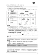
Page 13: ...rnate on the display The symbols on the display light up to identify the information shown 3 The default spin speed and temperatures values are shown The initial settings can be modified using the but...

Page 14: ...ogramme Once the option has been selected the cycle duration can be further re duced to an intermediate setting and a minimum setting and then returned to the initial duration by re peated pressing of...

Page 15: ...tion keep pressing the key repeatedly until the display shows 0 4 The Start Pause symbol flashes on and off until the cycle starts After the cycle starts the symbol re mains constantly lit 4 13 STARTI...

Page 16: ...to OFF 2 Unload the laundry from the drum 3 Leave the door ajar to allow the interior of the washer dryer to dry out 4 Turn off the water intake tap If during the initial spin speed setting stage the...

Page 17: ...knob to Off and disconnect the power supply plug from the socket Drain off the water see point 6 4 Pull the lever down and open the door Warning scolding hazard before opening the door check that the...

Page 18: ...ying must not exceed 4 Kg in weight The wa sher dryer is constructed to give the best results with loads which do not exceed 4 kg of dry weight of laundry When washing programmes for resistant fabrics...

Page 19: ...2 40 hours and ends with 0 00 hours Automatic drying with a choice of three residual moisture levels at the end of the drying cycle Iron dry garments are slightly damp ideal for easy ironing Cupboard...

Page 20: ...ics 5 4 INTERRUPTING OR CHANGING THE DRYING PROGRAMME 1 The drying programme can be interrupted by the same procedures as the washing programme 2 To end the programme and remove the laundry it is best...

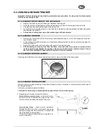
Page 21: ...use and dosages After descaling or removing rust from the drum carry out a few rinse cycles to remove all acid residues which might damage the appliance Never use cleaners which contain solvents There...

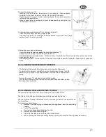
Page 22: ...n push it towards the cabinet until it snaps into place 6 5 CLEANING THE DETERGENT DRAWER The detergent drawer should be kept clean removing all solid deposits To simplify this operation completely re...

Page 23: ...le water to achieve the same washing and rinsing results 4 Water not pumped out Check that drain hose is not kinked drain pump not fouled 5 Water not pumped out after last rinse in delicate fabrics an...

Page 24: ...xcessive drying time is long enough appropriate drying time selected If the appliance still does not dry the laundry call the Service Centre to have the fan and drying ducts cleaned to remove any fluf...

Page 25: ...efreshing 800 2 Cold wash rinses and final spin at the selected speed Items with light dirt 30 40 800 2 Wash at 30 or 40 rinses and final spin at the selected speed Rinse and spin Max 6 Rinse and pump...

Page 26: ...NTAGE DES LAVE LINGE INT GRABLES FR INSTRUCCIONES DE INSTALACI N DE LAS LAVADORAS INTEGRABLES ES INSTRU ES DE MONTAGEM DAS M QUINAS DE LAVAR ROUPA INTEGR VEIS PT MONTAGEINSTRUCTIES VAN INTEGREERBARE W...

Page 27: ...the panel removing all the hinge and locking elements from the front make sure the wash ing machine is totally disconnected from the mains power supply Warning To fix the panel on the right hand side...

Page 28: ...ate for the magnet lock on the side opposite the hinges fig 7 5 Fix the panel to the washing machine following the instruc tions shown in fig 8 Adjusting the hinges If after applying the panel to the...

Page 29: ...rain pump to be cleaned if necessary In some cases the baseboard is not continuous but limited to the width of the washing machine In this case the kitchen baseboard can be fixed to the washing machin...

Page 30: ...ca 82kg 820mm 16mm 560mm 596mm 150mm 58mm 820mm 1 9 A B 2...

Page 31: ...2 2 3 3 12 12 11 11 7 7 10 10 8 8 9 9 2 2 1 1 3 3 4 4 6 6 5 5 4 5 4 1 1 2 3 2 3 C C 6 6 5 5 7 7 8 8 C A B A B C 9 D D 2 2 1 1 3 3 4 4 A B 3 A 3 B 3...

Page 32: ...mm 35mm 35mm 13mm 13mm 592 595mm 16 21mm 592 595mm e e e e e e e e Unterkante Lower edge C t inf rieur Lato inferiore Lado inferior Onderkant Unterkante Lower edge C t inf rieur Lato inferiore Lado in...

Page 33: ...1 1 2 2 3 3 1 1 2 2 3 3 1 1 7 8 9 2 1 2 4 3 5 6...

Page 34: ...9 10 11...

Reviews: