background image

Instructions for the installer

EN

41

POSSIBLE 

CONNECTION TYPES

CABLE TYPE

(if not present)

220

-

240 V

1N~

3-pole

3 x 1.5 

mm²

H05V2V2-F

•  Use H05V2V2-F cables withstanding temperatures of 90°C or higher.
•  The values indicated above refer to the cross-section of the internal

conductor.

•  The tightening torque of the screws of the terminal supply wires must be 1.5

- 2 Nm.

The aforementioned power cables are sized taking into account the coincidence
factor (in compliance with standard EN 60335-2-6).

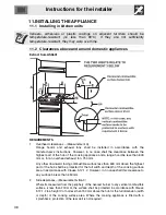
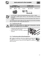
11.8 Positioning the skirt

WARNING: The skirt provided is an integral part of the product; it must be
fastened to the appliance prior to installation.

•  Position the skirt above the top, taking care

to align holes 

A

 with holes 

B

.

•  Secure the skirt to the top by tightening

screws 

C

.

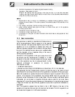
11.9 Positioning and levelling the appliance

After making the electrical and/or gas connections, properly level
the appliance on the floor to ensure better stability. Screw or
unscrew the bottom part of the foot until the appliance is stable and
level on the floor.

Summary of Contents for Oven

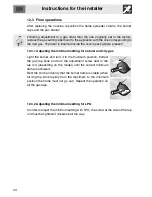
Page 1: ... the appliance set it functioning and carry out an inspection test Further information about the products can be found at www smeg com 1 INSTRUCTIONS FOR USE 4 2 SAFETY PRECAUTIONS 6 3 ENVIRONMENTAL CARE 8 4 GET TO KNOW YOUR APPLIANCE 9 5 AVAILABLE ACCESSORIES 11 6 USING THE COOKING HOB 15 7 USING THE OVEN 18 8 OVEN FUNCTIONS 23 9 CLEANING AND MAINTENANCE 30 10 EXTRAORDINARY MAINTENANCE 34 11 INST...

Page 2: ...ate with technical data serial number and brand name is located in an exposed position either in the drawer where present or on the back of the appliance A copy of the identification plate is included in the booklet It should be applied to an adjacent surface Do not remove this plate for any reason Before the appliance is put into operation all labels and protective films applied on external surfa...

Page 3: ... inside the oven If you intend to go away for a prolonged period of time close the mains gas tap or the gas cylinder tap Take care that no objects are stuck in the door of the oven Do not open the storage compartment where present when the oven is on and still hot The temperatures inside it may be very high If the surfaces are still very hot during cooking do not pour water directly onto the trays...

Page 4: ...etc they must only be used when the vehicle is stationary NOT FOR USE IN MARINE CRAFT CARAVANS OR MOBILE HOMES UNLESS EACH BURNER IS FITTED WITH A FLAME SAFEGUARD Where this appliance is installed in marine craft or in caravans it shall not be used as a space heater Install the appliance so that when opening the drawers or doors of units positioned at the level of the hob there is no possibility o...

Page 5: ... The improper use of tools can cause hazards This appliance must not be controlled using an external timer or remote control system Be aware of how rapidly the cooking zones heat up Do not place empty saucepans on the heat Danger of overheating Fats and oils can catch fire if they overheat You are therefore recommended not to leave the appliance unattended while preparing foods containing oils or ...

Page 6: ...als therefore compatible with the environment and recyclable Please help by disposing of the packaging correctly You can obtain the addresses of collection recycling and disposal centres from your retailer or from the competent local organisations Do not discard the packaging or any part of it or leave it unattended It can constitute a suffocation hazard for children especially the plastic bags Yo...

Page 7: ...Instructions for the user EN 9 4 GET TO KNOW YOUR APPLIANCE 1 Cooking hob 5 Fan 2 Control panel 6 Oven light 3 Oven seal 7 Storage compartment 4 Door Frame shelf ...

Page 8: ...this light goes out the preset heating temperature has been reached When the light flashes regularly it means that the temperature inside the oven is kept steady on the set level 4 Function selection knob The oven s various functions are suitable for different cooking modes After selecting the required function set the cooking temperature using the thermostat knob For more information on cooking f...

Page 9: ... tray for cooking foods which may drip Narrow rack useful for cooking small sized food such as meat It can be placed on top of a tray for cooking foods which may drip Tray useful for collecting fat from foods placed on the rack above Necessary when using the rotisserie Rotisserie supports They support the rotisserie rod Rotisserie rod for cooking chicken and all foods which require uniform cooking...

Page 10: ...e WOK pan stand should be placed on top of the hob pan stands as shown in the adjacent figure Make sure they are stable The WOK pan stand should only be used when cooking with a wok 5 2 Using the oven racks and trays The racks and trays are equipped with a mechanical safety lock which prevents them from being taken out accidentally To insert the rack or tray correctly check that the lock is facing...

Page 11: ...e rotisserie rod with the food The clip forks can be tightened using the fastening screws Place the rotisserie supports into the inserts at the corners of the tray The supports should be placed as shown in the adjacent figure Place the rotisserie rod on the supports Make sure the pins are correctly positioned on the shaped part of the supports ...

Page 12: ...serie rod into the hole of the rotisserie motor on the side of the oven At the end of cooking screw on the handle provided so that you can move the rod with the food on it readily Pour a little water in the drip tray to prevent smoke from forming Regular flashing of the thermostat indicator light during cooking is normal and indicates that the temperature inside the oven is being maintained consta...

Page 13: ...ter Simply press the knob and turn it anti clockwise to the maximum flame symbol until the burner lights If the burner does not light in the first 15 seconds turn the knob to 0 and wait 60 seconds before trying again After lighting keep the knob pressed down for a few seconds to allow the thermocouple to heat up The burner may go out when the knob is released in this case the thermocouple has not ...

Page 14: ...boil turn down the flame far enough to ensure that the liquid does not boil over If any liquid does boil over or spill remove the excess from the hob To prevent burns or damage to the hob during cooking all pans or griddles must be placed inside the perimeter of the hob All pans must have smooth flat bottoms If the flame accidentally goes out turn off the control knob and wait at least 1 minute be...

Page 15: ...Instructions for the user EN 17 6 4 Cookware diameters Burner Ø min cm Ø max cm 1 Auxiliary 12 14 2 Semi rapid 16 24 3 Rapid 18 26 4 Ultra rapid 20 26 5 Fish kettle burner Suitable oval containers ...

Page 16: ...fect the food with unpleasant odours 7 2 Cooling system The appliance is equipped with a cooling system which comes into operation as soon as a cooking function starts The fan causes a steady outflow of air that exits from the rear of the appliance and which may continue for a brief period of time even after the appliance has been turned off 7 3 Storage compartment The storage compartment is in th...

Page 17: ...am in the oven from causing problems open the door in two stages keep it half open 5 cm approx for 4 5 seconds and then open it fully If you need to access the food always leave the door open for as short a time as possible to prevent the temperature in the oven from falling and ruining the food To prevent excessive amounts of condensation from forming on the internal glass hot food should not be ...

Page 18: ...lue modification keys or to increase or decrease the setting by one minute for each pressure Press either of the value modification keys to display the current time Five seconds after last pressing the key the clock will start from the set time 7 7 2 Timer This function only activates the buzzer without stopping cooking Press and the display will light up as shown in figure 1 Within 5 seconds pres...

Page 19: ... time and every 12 minutes a new inside segment will light up figure 2 shows a cooking duration of 1 hour Once the required time is obtained cooking will start about 5 seconds after the last pressure on or The display will show the current time represented by the constantly illuminated segments and the minutes left to the end of the cooking time represented by the flashing segments each flashing s...

Page 20: ... time as soon as the current time reaches the set starting time all the inside segments will start to flash indicating that the oven has started cooking At the end of the cooking time the timer will switch the oven heating elements off the buzzer will start to sound and the numbers on the dial will flash To delete the entire set program hold down the central key for 2 seconds if cooking has alread...

Page 21: ...results even with very thick foods Perfect for large cuts of meat e g shin of pork FAN ASSISTED BOTTOM The combination of the fan with just the bottom heating element allows cooking to be completed more rapidly This system is recommended for finishing off the cooking of foods which are already well cooked on the surface but not inside which therefore need a little more heat Perfect for any type of...

Page 22: ...rts and biscuits Use dark metal moulds for desserts they help to absorb the heat better The temperature and the cooking duration depend on the quality and consistency of the dough Check whether the dessert is cooked right through at the end of the cooking time put a toothpick into the highest point of the dessert If the dough does not stick to the toothpick the dessert is cooked If the dessert col...

Page 23: ... that you preheat the oven before grilling We recommend placing the food at the centre of the rack 8 2 To save energy To save energy while using the appliance the following instructions may be followed Stop cooking a few minutes before the time normally used Cooking will continue for the remaining minutes with the heat which has accumulated inside the oven Reduce any opening of the door to a minim...

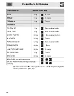
Page 24: ...1 2 kg Fan assisted static PORK SHOULDER 1 2 kg Turbo ROAST RABBIT 1 2 kg Circular TURKEY BREAST 1 5 kg Fan assisted static ROAST PORK NECK 2 kg Turbo ROAST CHICKEN 1 2 kg Turbo GRILLED MEATS PORK SAUSAGES 1 2 kg Fan assisted grill PORK CHOPS 1 2 kg Grill HAMBURGERS 0 8 kg Grill BACON 0 8 kg Fan assisted grill ROTISSERIE CHICKEN 1 1 2 kg Rotisserie grill FISH SALMON TROUT 1 2 Kg Fan assisted botto...

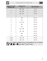
Page 25: ...TIME IN MINUTES 1 220 230 50 60 1 220 230 40 2 180 190 70 80 2 180 190 70 80 2 180 190 90 100 2 180 190 70 80 2 180 190 80 90 2 180 190 190 210 2 180 190 60 70 1ST SURFACE 2ND SURFACE 3 250 280 7 9 5 6 4 250 280 15 5 4 250 280 9 5 3 250 280 13 3 250 280 70 80 2 150 160 35 40 ...

Page 26: ...ic SHORT PASTRY 0 5 kg Fan assisted bottom JAM TARTS 1 2 kg Turbo PARADISE CAKE 1 2 kg Fan assisted static CREAM PUFFS 0 8 kg Turbo LIGHT SPONGE CAKE 0 8 kg Circular RICE PUDDING 1 kg Turbo BRIOCHES 0 6 kg Circular BRIOCHES on multiple runners SHORT PASTRY BISCUITS on multiple runners The times indicated in the following tables do not include the preheating times and are provided as a guide only ...

Page 27: ...50 280 6 10 2 190 200 25 30 2 180 190 15 20 2 160 50 60 2 160 30 35 2 160 170 20 25 2 160 20 25 2 160 55 60 2 150 160 40 50 2 150 160 45 50 2 160 40 50 2 160 25 30 1 and 3 160 170 16 20 1 and 3 160 170 16 20 For cooking on multiple runners we recommend that you use functions and only and the 1st and 3rd runners ...

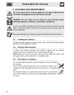
Page 28: ...ven surfaces in good condition they should be cleaned regularly after use Let the appliance cool first 9 2 Ordinary daily cleaning To clean and preserve stainless steel surfaces always use only specific products that do not contain abrasives or chlorine based acids How to use pour the product onto a damp cloth and wipe the surface rinse thoroughly and dry with a soft cloth or a microfibre cloth 9 ...

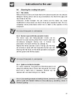
Page 29: ...oved for easier cleaning Wash them in warm water and non abrasive detergent making sure to remove any encrustation then wait until they are perfectly dry Replace the flame spreader crowns making sure that they are correctly in place with their respective burner caps and ensuring that the holes A in the flame spreaders are aligned with the igniters and thermocouples Do no wash these parts in a dish...

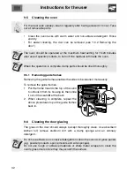
Page 30: ...es Removing the guide frames enables the sides to be cleaned more easily To remove the guide frames 1 Pull the frame towards the top of the oven to unhook it from its housing A then slide it out of the seats B at the back 2 When cleaning is complete repeat the above procedures to put the guide frames back in 9 6 Cleaning the door glazing The glass in the door should always be kept thoroughly clean...

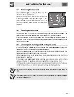
Page 31: ...leaning self cleaning panels catalysis cycle If the self cleaning panels are dirty primarily with small amounts of grease a heating cycle can be executed to regenerate them Clean the base and the roof liner first with a microfibre cloth soaked in water and neutral washing up liquid then rinse thoroughly Set a regeneration cycle by selecting a fan assisted function at the maximum temperature for on...

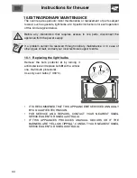
Page 32: ...through ordinary maintenance or in case of other types of fault contact your local technical support centre 10 1 Replacing the light bulbs Remove the bulb protector A by turning it anticlockwise and replace bulb B with a similar one Re fit bulb protector A Use only oven bulbs T 300 C IT IS RECOMMENED THAT THIS APPLIANCE BE SERVICED ANNUALLY BY A QUALIFIED TECHNICIAN FOR SERVICE AND REPAIRS CONTACT...

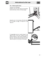
Page 33: ...them until they engage Grasp the door on both sides with both hands lift it forming an angle of around 30 and remove it To reassemble the door put the hinges in the relevant slots in the oven making sure that grooved sections C are resting completely in the slots Lower the door and once it is in place remove the pins from the holes in the hinges ...

Page 34: ...pliance and a range hood be less than 600 mm or for an overhead exhaust fan 750 mm Any other downward facing combustible surface less than 600 mm above the highest part of the hob shall be protected for the full width and depth of the cooking surface area in accordance with Clause 5 12 1 2 However in no case shall this clearance to any surface be less than 450 mm 2 Side clearances Measurements B C...

Page 35: ...checking the gas pressure is supplied either with the regulator or as a separate fitting in the case of ULPG propane appliances Connection of the appliance to the gas supply must be in accordance with the requirements of AS5601 A BSP connector at the inlet is recommended and the gas supply line to the appliance must be of adequate length to allow sufficient withdrawal of appliance for service or d...

Page 36: ...lues indicated in the paragraph 3 2 Burner and nozzle characteristics table 11 5 Ventilation in the room containing the appliance The room containing the appliance should have a permanent air supply in accordance with the standards in force The room where the appliance is installed must have enough air flow needed for the regular combustion of gas and the necessary air change in the room itself Th...

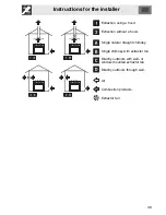
Page 37: ...traction using a hood Extraction without a hood Single natural draught chimney Single chimney with extractor fan Directly outdoors with wall or window mounted extractor fan Directly outdoors through wall Air Combustion products Extractor fan ...

Page 38: ...oth of these must be of the same type and connected to the power cable in accordance with current standards The socket must be accessible after the appliance has been built in NEVER UNPLUG BY PULLING ON THE CABLE Should the earthing wire need replacing it must be longer than the conducting wires so that if the plug is torn off the power cable it is the last to be detached Avoid use of adapters and...

Page 39: ...o account the coincidence factor in compliance with standard EN 60335 2 6 11 8 Positioning the skirt WARNING The skirt provided is an integral part of the product it must be fastened to the appliance prior to installation Position the skirt above the top taking care to align holes A with holes B Secure the skirt to the top by tightening screws C 11 9 Positioning and levelling the appliance After m...

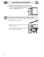
Page 40: ...plied into the wall at a height h of 800 mm from the floor The installer must provide the hook bolt when installing the appliance 2 Attach the snap hook to the chain 3 Attach the end of the chain to the hook bolt fastened in the wall 4 Finally connect the snap hook to the appropriate hole on the back of the appliance ...

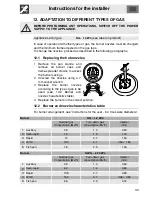
Page 41: ...rew the nozzles using a 7 mm socket wrench 3 Replace the burner nozzles according to the type of gas to be used see 12 2 Burner and nozzle characteristics table 4 Replace the burners in the correct position 12 2 Burner and nozzle characteristics table For burner arrangement see Instructions for the user 6 4 Cookware diameters Burner NG 1 0 kPa Nominal gas Consumption MJ h Turn down gas consumption...

Page 42: ...ng the minimum setting for natural and city gas Light the burner and turn it to the minimum position Extract the gas tap knob and turn the adjustment screw next to the tap rod depending on the model until the correct minimum flame is achieved Refit the knob and verify that the burner flame is stable when turning the knob rapidly from the maximum to the minimum position the flame must not go out Re...

Page 43: ......

Page 44: ...914774767 A ...

Reviews: