background image

INSTALLATION  -  17

91477A688/A

e

For the Australian/New Zealand market:

The circuit breaker incorporated in the fixed 
connection must comply with AS/NZS 3000.

Connection with plug and socket

Make sure that the plug and socket are of the 
same type.
Avoid using adapters, gang sockets or shunts as 
these could cause overheating and a risk of 
burns.

Section cut from the countertop

Safety instructions for positioning and 
installation

• Installation can be carried out on various 

materials such as masonry, metal, solid 
wood or plastic laminated wood as long as 
they are heat resistant (>90°C).

• Veneers, adhesives or plastic coatings on 

adjacent furniture should be temperature-
resistant (>90°C), otherwise they might 
warp over time.

• If the piece of furniture does not have the 

required recess opening, either it will have 
to be cut or masonry work carried out by a 
competent technician.

• The minimum clearance between exhaust 

hoods and the cooking surface must be at 
least the distance indicated in the exhaust 
hood installation instructions.

• The minimum clearances must also be 

respected for the edges of the hob on the 
back as indicated in the assembly 
instructions.

• If the appliance is to be installed above an 

oven, the oven must be fitted with a cooling 
fan.

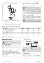
Appliance overall dimensions (mm)

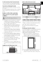
Built-in cabinet dimensions (mm)

*If there is a kitchen unit positioned above the
hob. In the case of a hood, refer to
the measurements indicated in the relative 
manual.

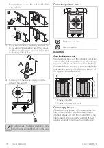
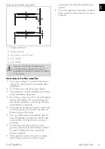
Fastening to the built-in cabinet

To prevent leakage of liquid between the frame 
of the hob and the countertop, place the 
adhesive seal provided along the entire outer 
edge of the hob before assembly.
1. Refer to the dimensions indicated in the 

figure, bearing in mind that the long front 
and rear sides must be flush with the hole.

2. Press lightly to make the seal stick to the 

edge around the hole in the worktop. The 

See General safety instructions.

X (mm)

Y (mm)

292

494

A (mm)

B (mm) C (mm)* D (mm)

E (mm)

min 150 min 460 min 750 20 - 70

min 50

Summary of Contents for PGA32G

Page 1: ...om These instructions apply only to the destination countries listed on the appliance s data plate This is a class 3 built in hob PRECAUTIONS General safety instructions Risk of personal injury During...

Page 2: ...the flames for example with a lid or a blanket Do not cook foods in closed tins or containers or plastic containers Do not insert pointed metal objects cutlery or utensils into the slots in the applia...

Page 3: ...reful Fire hazard Never leave objects on the cooking surfaces DO NOT FOR ANY REASON USE THE APPLIANCE AS A SPACE HEATER Cooking vessels or griddle plates should be placed inside the perimeter of the h...

Page 4: ...authorised personnel Have the electrical connection performed by authorised technical personnel Installation using a hose must be carried out so that the length of the hose does not exceed 2 metres w...

Page 5: ...nt to provide complete disconnection in category III overvoltage conditions pursuant to installation regulations Appliance purpose This appliance is intended for cooking food in the home environment E...

Page 6: ...und in a separate document together with the product instructions This information can be found in the Product information sheet that can be downloaded from the page for the specific product on the we...

Page 7: ...sition to turn off the burners Accessories Not all accessories are available on some models The accessories intended to come into contact with food are made of materials that comply with the provision...

Page 8: ...over Using the accessories Raised pan support The raised pan supports should be placed on the hob pan supports Make sure they are placed properly Using the hob All the appliance s control and monitor...

Page 9: ...for more than 40 minutes Correct positioning of the flame spreader crowns and burner caps Before lighting the hob burners make sure that the flame spreader crowns are correctly positioned in their ho...

Page 10: ...no detergent left on the cooking surface as it might undergo an aggressive reaction when heated up and could modify the structure of the cooking surface Food stains or residues Light coloured marks f...

Page 11: ...ith the requirements of AS5601 A 1 2 BSP connector at the inlet is recommended The gas supply line to the appliance must be of an adequate length to allow it to be withdrawn sufficiently for maintenan...

Page 12: ...nection on the gas cylinder following the guidelines set out in the standards in force The supply pressure must comply with the values indicated in the Burner and nozzle characteristics table Room ven...

Page 13: ...gas to be used see the Burner and nozzle characteristics table 3 Replace the burners in their respective housings Adjusting the minimum setting for natural or town gas 1 Light the burner and turn it t...

Page 14: ...for any reason The appliance must be connected to ground using a wire that is at least 20 mm longer than the other wires The appliance can work in the following modes 220 240 V 1N fig 1 Fixed connect...

Page 15: ...ance between exhaust hoods and the cooking surface must be at least the distance indicated in the exhaust hood installation instructions The minimum clearances must also be respected for the edges of...

Page 16: ...or other built in appliances must be enough to ensure sufficient ventilation and air discharge If installed above an oven a space must be left between the bottom of the hob and the top of the applianc...

Page 17: ...ked flames to search for leaks Turn on all the burners separately and at then all together to make sure that the gas valve burner and ignition are working properly Turn the burner knobs to the minimum...

Reviews: